MIL-STD-1275E - Voltage Tests, Waveforms, & Download


MIL-STD-1275E
MIL-STD-1275E applies to equipment connected to 28 VDC vehicle distribution systems which are common across military ground vehicles. Separate standards exist for ships and aircraft(1). The goal of this standard is to provide common testing criteria across different vehicles ensuring a "common" testing criteria.
This standard is available for download through the link provided directly from the department of defense (DOD) Defense Standardization program or a quick search providing access to a variety of standards and requirements.
What is MIL-STD-1275E?
Military Standard 1275E is a series of tests that including voltage surges, spikes, and ripples that apply to 28 VDC military ground vehicles designed to evaluate impact on EUT/DUT given the operating electrical environment.
The first MIL-STD-1275 standard was released in 1976, the most recent being from 2013. Additional information on changes between the different versions can be found in the "Background" section of the Review of MIL-STD-1275 Requirements article by Interference Technology.
Major Tests - Voltage Compatibility Requirements
The voltage compatibility requirements provided in § 5.1 provide guidance under which the equipment is expected to run. It breaks down the tests into a few different categories:
- §5.1.1 Steady State Operation (Voltage Ripple)
- §5.1.2 Starting Operation (IES & Cranking Surges)
- §5.1.3 Transient Disturbances (Voltage Spike & Injected Surge)
Throughout this post additional information will be provided based on §5.3 voltage compatibility verification methods providing setup overview information as well as testing criteria.
Operational Voltage Range & Ripple

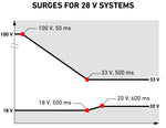
The operational voltage requirements provided in §5.3.1.1 reference a voltage envelope where the EUT is subjected to both low and high voltage at associated duration lengths.
The image on the right based upon information provided in standard illustrates the main criteria for this test minus the time component. Outside of the associated voltage ranges (indicated in the grey area) the utilization equipment may be damaged or become inoperable. The associated solid line shown in the image includes the ripple voltage which will be discussed in the following section.
Voltage Ripple
A voltage ripple in the context of MIL-STD-1275E can be thought of as variations beyond the fixed DC voltage during normal operation of DC equipment. These type of events can be caused by signals being coupled onto input power leads.

The voltage ripple requirements are based on MIL-STD-461 CS101 maximum peak-to-peak ripple voltage limits with the same values at 150kHz used up to 250kHz. MIL-STD-461 can be download from from the Quick Search Assist from the DoD.
The associated image from CS101 has been adjusted to show the 28 volts or below test level with the extend range of up to 250kHz. It is important to note that the same equipment used in CS101 may not be able to be used for MIL-STD-461 if the frequency range and associated levels are not met. The test levels indicated in MIL-STD-461 keep a constant dBuV limit level past the 150kHz frequency range.
Starting Disturbances - IES & Cranking Surges

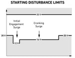
Initial engagement surge (IES) and cranking surges are commonly are caused by changes in system voltage from typical operating range caused by the engagement of the engine starter and subsequent engine cranking.
The image provided is based upon Figure 6 and includes the associated disturbances with associated voltage levels. The solid line indicates the ripple voltage which varies by different events. Timing requirements are also specified within the standard with IES maximum duration of 1 second and cranking surges 30 seconds.
Injected Voltage Transient Spikes & Surges
Transient tests in accordance with this standard have crossover with both military and automotive tests. This can be seen with voltage surge waveform and test requirements as well as emitted spikes which directly references SAE J1113-42. SAE J1113-42 2010 has subsequently been replaced by ISO 7637-2 which includes conducted emissions transient tests.
The voltage surges and spikes in this standard are commonly done using a specially designed transient generator, such as the Montena PG1275E.
The associated video shows:
- How to setup the Generator
- Modifying Testing Parameters
- Utilizing Montena Software
- Calibration/Pulse Verification
The transient injected voltage spike, surge, and associated monitoring tests all utilize a 5uH LISN/AN to simulate the additional vehicle wring harness. Additional information on different types and applications of Line Impedance Stabilization Networks can be found here.
Spikes §5.3.3.1.1
Voltage spikes can be thought of an energy-limited transient waveforms having a duration less than or equal to 1ms. Spikes can be caused from interaction of the power delivery system and switching of reactive loads or mismatch in impedance between wiring harness and equipment.
The image on the left shows the spike waveform according MIL-STD-1275E as well as the characteristics along the side. Both the positive and negative voltage spikes are applied to the EUT/DUT with pulse requirements meeting criteria and setup placed within this section.

Verification of the waveform is required prior to running the test with a load whose resistance matches the source impedance of the transient generator.

The associated images illustrates a voltage spike verification setup conducted prior to testing, it includes:
- Differential Voltage Probe
- Digital Storage Oscilloscope
Surges §5.3.3.2.1
Surges within this standard can be a result of switching reactive loads or sudden disconnection, however most commonly relate to the alternator. The positive surges are often called simply "alternator load dump" in automotive applications. This occurs when charging the battery and the connection is suddenly broken or interrupted. The alternator unable to account for the sudden loss of the load, deliveries the stored energy to the vehicles electrical system.
The associated positive waveform based upon the standards criteria can be seen on the left. The positive surge test requires 5 pulses with a time between pulses of 5 seconds.

Verification of the waveform is required prior to running the test with a load that matches whose resistance matches the source impedance of the transient generator.

The associated images illustrates a common surge pulse verification setup conducted prior to testing, it includes:
- Calibration Resistor
- Differential Voltage Probe
- Digital Storage Oscilloscope
References:
1)Ferguson, S., 2022. Review of MIL-STD-1275 Requirements | Interference Technology. [online] Interference Technology. Available at: <https://interferencetechnology.com/review-of-mil-std-1275-requirements/> [Accessed 28 July 2022].
A. Singh, "Load Dump and Cranking Protection for Automotive Backlight LED Power Supply" Texas Instruments, 2015. Accessed July 28, 2022. [Online]. Available: https://www.ti.com/lit/an/snva681a/snva681a.pdf
MIL-STD-1275:2013(E) - "Characteristics of 28 Volt DC Input Power to Utilization Equipment In Military Vehicles"

