What are Line Impedance Stabilization Networks (LISNs)?
Line Impedance Stabilization Networks
There are three types of LISNs, with V-LISNs (also called Artificial Mains Network) being most commonly used in EMC. All LISNs regardless of inductance or application have an electrical path where measurements will be made as well as a monitoring port for connection to an analyzer.
What is a LISN?
A line impedance stabilization network (LISN) is a measurement device used in emissions testing to monitor RF signal levels over a given frequency range while providing a constant impedance value.
While these devices are used in different ways, all share some similar charteristics. These type of devices are designed to have three main functions:
- 1) Provide Stable Impedance (50Ω) on mains
- 2) Block RF Signals on Mains from Entering EUT
- 3) Provides Measurement Port[1]
Characteristics of LISNs
There are a few key criteria that differentiate LISNs and allow for compliance to a particular standard or requirement, these include impedance, phase angle, insertion loss, frequency, power limitations, amongst others. It is best practice when evaluating different LISNs to reference data sheet and manufacturer resources to ensure compliance.
The impedance, phase angle, and insertion loss requirements are provided over a given frequency range at set levels by the associated standard.
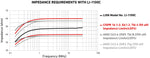
The above graph show the impedance requirements of both CISPR 16-1-2 and ANSI C63-4 with the data for the Com-Power LI-1100C 50 uH LISN.
Emissions Setup
LISNs in conducted emissions will be placed before the equipment under test and connected to the power mains or source. Immunity applications can utilize LISNs in different ways depending on the underlying requirement.
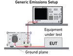
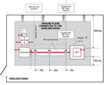
The associated image illustrates a generic conducted emissions setup using the Rhode and Schwarz ENV216 connected to a receiver to make emissions measurements. Depending on the model of LISN an isolation transformer can be required between the power input and LISN.
What are the types of LISNs?
The three main types of LISNs are Delta-LISNs, V-LISNs, and T-ISNs. V-LISNs (typically just called LISNs) come in two categories, 5uH and 50uH, and are the most commonly used.
Types of LISNs
Each type of LISN provides different capabilities, with T-ISN (often referred to as just ISNs) being used mainly or data/IO line measurements. V-LISNs designed for power lines can either have an individual line per unit, or lines combined in a single unit with a plug type connection.
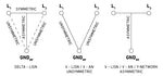
The associated image from Schwarzbeck shows the three main types topology.
Delta-LISN: Symmetric & Asymmetric (line-to-line) Power Lines
V-LISN: Unsymmetrical (line-to-ground) Power Lines
T-ISN: Asymmetric (mid point line-to-line) Common Mode Data/IO Lines
Inductance in LISNs 5uH vs 50uH
The inductance values used in the design of the LISNs are based upon the anticipated inductance of the power system which the equipment will be connected. For large systems and commercial (includes large aircraft) requirements 50 micro-Henry is often used whereas, for smaller systems (notably automotive) 5 micro-Henry is common.
A generic inductance value of a single straight cable can be calculated using the wire diameter, wire length, and permeability. A digital calculator can be accessed by clicking here. While most cabling does involve some curve or winding, generally the larger length and diameter the higher the inductance. It is best practice to reference the standard as the table below is generic, individual product requirements can vary.
The value of 50 micro-henry was selected as an inductor by MIL-STD-461 as it represents the inductance of 50 meters of power wiring systems common on a ship or cargo aircraft.
The below chart provides a reference for common emissions requirements and the typically used inductance requirements. Some standards, as with MIL-STD-461, provides a caveats allowing for both to be used in certain sections.

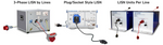
Line & Socket LISNs
Line impedance stabilizations come in two different configurations, one with a socket built-in and another with connectors for each line(s). Its common for 50 uH LISNs designed for commercial applications, particularly true for single phase equipment under test, to have a built-in socket.
Impedance Stabilization Networks (ISNs)
Impedance stabilization networks, commonly just called ISNs, are devices that can be used to measure emissions on different data lines as well as used in conducted RF applications. These networks will generally vary by cable types, IE coaxial, RJ11, RJ45, etc.
Why are LISNs used?
LISNs are used to make conducted emissions measurements as well as provide a stable impedance used to replicate power lines associated with the EUT/DUT.
How to use LISNs
Line impedance stabilization networks are commonly used for two main applications, emissions measurements as well as conducted RF immunity testing. It's common for a single model of LISN to provide capabilities for both uses.
Conducted Emissions
Conducted emissions standards specify LISN design requirements, frequency ranges covered, as well as conducted limits in quasi-peak and average measurements commonly in dBμV. They often differentiate testing criteria based upon the type of product or application, this can been seen with FCC Part 15 Subpart B which can be accessed by clicking here.
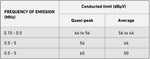
While some standards cover entire frequency ranges consecutively, other have gaps between set ranges. The associated image shows the test levels for FCC Part 15 provided by the FCC website. The associated test levels are designed for all digital devices, minus those that are considered Class A.
They also regulate how the voltage measurements are made, commonly between each power line and ground at the power terminals with V-LISNs.
Conducted Emissions Testing Guides
The process of running a conducted emissions test can vary based on the equipment used, test requirement, and power of the EUT. The below guides and applications notes provide additional information.
Michigan State University - Conducted Emissions
TekBox - How to correctly use a spectrum analyzer for EMC pre-compliance tests
Measurements steps using LISNs
When conducting measurements using LISNs it is best practice to run the equipment prior to connecting the analyzer to protect the RF input.
- Leave the RF output of the LISN unconnected
- Connect the EUT to the LISN
- Connect the LISN to the isolation transformer (if used)
- Power on the EUT
- Check the RF output of the LISN using analyzer with a 20 dB attenuator or transient limiter
- Connect the RF cable from LISN output to the spectrum analyzer input
- Carry out the conducted noise scan
- Disconnect the RF cable
- Power off the EUT
LISNs in BCI Testing
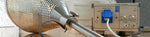
Both the substitution and closed loop methods of Bulk Current Injection Testing including ISO 11452-4 and MIL-STD-461 CS114 requirements utilize LISNs. When the LISNs are used in these type of applications they're typically used to provide a simulate impedance as well as utilize other features of these devices. LISNs used in BCI Test will have frequency ranges matching those of the immunity requirement, typically between 10 kHz to 400 MHz.
The below image illustrates a setup based on ISO 11452-4 requirements which shows the LISN (also called artificial networks) are used.
What is a 50uH LISN?
50uH LISNs are conducted emissions measurement devices providing a 50 micro-henry inductance value and stable 50 Ohm impedance commonly used in AC commercial applications and large electrical power systems.
50uH LISNs
LISNs with a 50uH inductor are commonly used for commercial and military conduced emissions measurements. As mentioned above the larger inductance value is used to replicate larger electrical power systems.
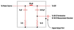
The image on left from MIL-STD-461G, provides a schematic for the required 50uH LISN. The underlying testing requirement will place requirements on the design of LISN often requiring different LISNs based on the application or standard.
MIL-STD-461 LISNs
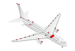
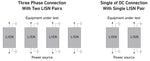
MIL-STD-461G specifies 50uH LISN and under appendix A allows for 5uH LISNs under certain conditions for sections CE101 and CE102. MIL-STD LISNs are typically housed individually by lines, with four units typically being used to provide monitoring for three phase applications. The below image illustrates how single line LISNs are used for both single phase and three phase applications.
What is a 5uH LISN?
5uH LISNs are conducted emissions measurement devices providing a 5 micro-henry inductance value and stable 50 Ohm impedance commonly used in DC automotive and avionic applications.
5uH LISNs
5μH LISNs/ANs are typically used in automotive and avionic testing where smaller electrical power systems are common. In the automotive industry a wide variety of new requirements have been put in place for LISNs used in testing electric or hybrid vehicles. These changes are commonly in testing high voltage cabling, requiring new designs for compliant monitoring of emissions levels.
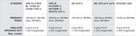
The below image provides an overview of some of the most common 5 uH requirements and doesn't indicate if additional accessories such as 10 uF capacitors are required.
There are many different options for available for 5 uH LISNs, depending on the testing standard specific models will be needed for compliance.
The video on the Teseq HV-AN 150 walks though how the different jumper configurations can be used to meet different requirements. The video includes:
- 5uH LISN/AN Overview and Capabilities
- CISPR 25 Configuration Including Enclosure
- RTCA/DO-160 Setup with 10uF Capacitor
CISPR 25
CISPR 25 edition 4.0 is the current version was released 10/27/2016 and can be purchased through the IEC webstore. This standard pertains to both vehicles and boats and this newest versions includes specific requirements for electric and hybrid vehicles. The majority of information regarding line impedance stabilization networks is included in section 6, with additional information in annex E and annex I.
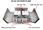
Edition 4 placed new requirements for low voltage (LV) testing below 60 volt and high voltage (HV) above the 60 volt threshold. In addition to the different designs, CISPR 25 now also requires a shielded metal enclosure to encompass both Artificial networks (ANs). The below image shows the Teseq HV-AN 150's in the SME HV-AN 150 for compliant emissions testing to CISPR 25 edition 4.
RTCA/DO-160
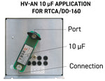
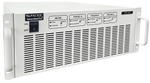
5μH LISNs are required for RTCA/DO-160 testing to have an additional 10uF capacitor. These capacitors are typically added externally and are required for compliant measurements. The associate image on the right shows the installation of the Teseq EXT 10uF capacitor.
The Teseq HV-AN 150 LISNs/ANs can be modified through the jumper methodology to meet requirements of many 5uH standards. Compliance to DO-160 should be confirmed with the manufacturer prior to purchasing.
5uH and 50uH values are used to describe the associated inductance value of associated LISN, with the larger value often reflecting larger associated cable lengths.
LISNs are typically placed after the power supply prior to the DUT/EUT test.
LISN stands for Line Impedance Stabilization Network often times also called Artificial Network (AN)
References:
Federal Register :: Request Access. (n.d.). Unblock.federalregister.gov. https://www.ecfr.gov/current/title-47/chapter-I/subchapter-A/part-15/subpart-B
How to use spectrum analyzers for EMC testing_V1_3_20220409.docx How to correctly use spectrum analyzers for EMC pre-compliance tests. (n.d.). Retrieved January 29, 2025, from https://www.tekbox.com/product/AN_spectrum_analyzers_for_EMC_testing.pdf
LISN_Basics and Overview_20220411.docx Line Impedance Stabilization Networks -Basics and Overview. (n.d.). https://www.tekbox.com/product/LISN_Basics_and_Overview.pdf
Super User. (2025). LISN / AMN. Schwarzbeck.de. http://www.schwarzbeck.de/en/lisn-line-impedance-stabilisation-networks.html
