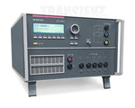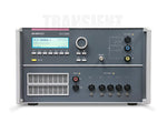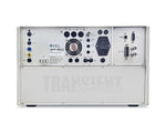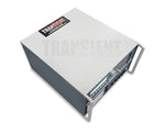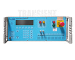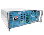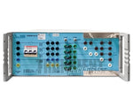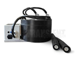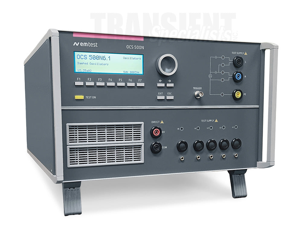
EM Test OCS 500N6.1
Rent Slow Oscillatory Wave Generator
Features
- 100 kHz & 1 MHz 3 kV Waveform Generator
- Built-in Single-Phase CDN 250 V/ 16 A AC & DC
- Compliant to ANSI C37.90 & IEC 61000-4-18
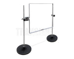
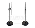
- Antenna for IEC 61000-4-10 Available
- Current ISO 17025 Accredited Calibration
- OCS 500N6.1
- Laptop with Charger
- Power Cord
- Printed Manual
- Calibration
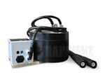
- ESC EUT Power in Cord
- ESA 1.6 EUT Supply adapter
- USB Cable
- USB Stick
- Calibration Certificate
- (3) pcs 2 meter black,blue yellow banana cable
- 1 pc Black 24 inch banana cable
- Shipping Case
Description
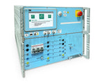
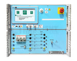
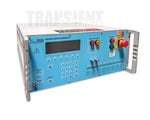
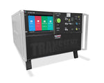
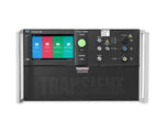
The EM Test OCS 500N6.1 is a transient immunity generator designed for damped oscillatory wave testing of electrical and electronic equipment. The system generates 100 kHz and 1 MHz damped oscillatory waveforms up to 3 kV, supporting immunity testing in accordance with IEC 61000-4-18 and related EMC requirements.
For damped oscillatory wave testing, the OCS 500N6.1 provides an open-circuit voltage range from 250 V to 3,000 V, a nominal 75 ns rise time, and a 200 Ω source impedance. Both positive and negative polarity testing are supported, with programmable repetition rates for performing controlled and repeatable immunity testing.
An integrated single-phase coupling decoupling network supports powered equipment during testing, allowing damped oscillatory transients to be coupled directly onto the DUT power lines. Programmable synchronization provides additional control over the point on the AC waveform at which the transient is applied.
The OCS 500N6.1 is well suited for laboratories performing EMC immunity testing on industrial, commercial, and electronic equipment. Its integrated design combines waveform generation, coupling, and programmable test control in one system, helping simplify test setup while providing repeatable damped oscillatory wave testing for IEC 61000-4-18 applications.
- Specifications:
- Model
- OCS 500N6.1
- Oscillation frequency:
- 100 kHz and 1 MHz +/- 10 %
- Voltage (o.c.) at HV output
- 250 V - 3,000 V +/- 10 %
- Voltage (o.c) at line output
- 250 V - 2,500 V +/- 10 %
- Rise time
- 75 ns +/- 20 %
- Decaying
- Peak 5 to be > 50% of peak 1 value
- Peak 10 to be < 50% of peak 1 value
- Source impedance
- 200 ohm +/- 20 %
- Polarity
- Positive, negative
- Repetition rate
- Max. 50 /s for 100 kHz and Max. 500 /s for 1 MHz
- Burst duration
- At least 2 s
- Trigger Circuit�
- Release of pulses
- Automatic, manual, external
- Synchronization
- 0 - 360 degrees, resolution 1 degree
- Output
- Direct
- Via HV-safety lab connectors
- Coupling mode
- Line to line Line(s) to ground (PE)
- DUT supply 1ph-16 A
- AC: 250 V/16 A; 50/60 Hz
- DC: 250 V/16 A
- CRO trigger
- 5 V trigger signal for oscilloscope
- Test Routines
- Quick Start
- Immediate start; easy-to-use and fast
- Standard Test routines
- As per IEC 61000-4-10, Level 1 - 5
- User Test routines
- Change polarity after n pulses
- Change coupling after n pulses
- Change voltage after n pulses
- Change phase angle after n pulses
- General Data
- Dimensions, weight
- 6 HU, approx. 28 kg (1-phase)
- Supply voltage
- 115/230 V +10/-15%
- Fuses
- 2 x T 2 AT (230 V);
- 2 x T 4 AT (115 V)

info@transientspecialists.com