How to Use & Select the Right Transient Generator

Transient Generators
Transient test generators or transient immunity systems encompass a wide range of different applications including commercial, automotive, and military requirements. The main purpose of these types of test systems is to create fast rise time high energy waveforms and pulses coupled onto power, data, and communication lines. The information provided below will focus on the commercial immunity requirements based around the common IEC standards.
What are Transient (Pulse) Generators?

While there are many manufacturers and configurations of transient test systems, all have a few key features:
- Provide conducted immunity transient pulses
- Include interface for modifying testing parameters
- Allow for both power-off and power-on testing
Major Manufacturers
While there are many companies both domestically and internationally that manufacture or distribute these conducted immunity test systems, below are the recommended vendors and best points of contact.


Common Test Methods
How testing is conducted will determine the necessary connections and auxiliary equipment needed. The two main methods which are used with these conducted immunity test systems is either through the coupling decoupling network (CDN) or through the direct-out connections. The direct-out can be used for testing when the EUT/DUT is not powered-on, or with the use of a capacitive coupling clamp (CCL).
These methods are commonly reference by the underlying standard or associated test plan and testing should be conducted accordingly.
Power-on Testing - Testing Through the CDN
Testing, while the equipment under test is operational, is commonly done and offers insight into the impact the event will have on functionality of the EUT.

The associated image with the AXOS5 is a typical setup using mains power. The pulse generator requires its own power to run requiring two connections to allow for operation.
It is common to have either an EUT supply adapter from the output of the CDN (usually built into the generator) or EUT power broken out by lines allowing for easy connection to the EUT/DUT. In the image on the left this can be seen with a female adapter coming from the right side of the test system.
While each system has CDNs with different power limitations, it's common to have both a AC and DC capabilities. Prior to testing, the voltage and current of the EUT must fall within these limits or damage to the system will occur. There are a variety of power CDNs available on the market available up to 200 Amps.

Testing with a Power Supply
While not always needed some manufacturer's recommend an isolation transformer to limit any residual current, ensuring any circuit breakers will be tripped. The isolation transformer is placed between the mains power supply and EUT Supply Input as seen the image on the right from the Axos User Manual.
As discussed above the power going into the CDN will be used power the EUT/DUT. Should the associated equipment run off of anything other than standard mains power a source will be needed to allow the EUT operation. When using an external supply it is important to remember that the AC capabilities of the CDN may be different then the DC, checking values for both prior to running the test.
Testing via Direct Out
Testing using the direct out is commonly done for electrical fast transient (EFT) testing using a capacitive coupling clamp to test data and communication ports. Surge testing can also be done from the direct out which is typically located on the backside of most test systems.
The direct pulse output cannot be used for power line testing or connected to a CDN. Any power-on testing must be done through the CDN or damage to the associated equipment will occur.

The image on the left shows how the direct pulse output on the EM Test NX5 is connected to a capacitive coupling clamp used for EFT testing.
The diagram shows how the EFT pulses come from the generator into the associated communication cabling going towards the EUT/DUT, in this case a laptop.
Selecting Testing Criteria

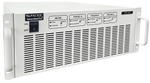
Testing criteria can be selected either through the front panel or by using the associated software. Often times the generators themselves indicate which modules or capabilities are installed via the front panel as shown on the IMU-MGS display on the right.
Many of the most common standard test routines can also be accessed via the front panel display of many systems providing an effective solution for many requirements.
Testing using Software
Proprietary software is offered with many test systems, allowing for additional programmability and increased automation in the testing process. Often it can be acquired at the time the generator is purchased or after the fact. Some systems offer more "basic" complementary software allowing for the most common tests to be run remotely at no additional charge.
The video using the EM Test NX5 includes:
- Connections to the front and back of unit
- Methods for connecting to EUT/DUT
- Adjusting Testing Criteria from Display
- CCL Connections to the System
- Using Software to Change Parameters
Line Coupling Path

The two methods by which EUT/DUT are exposed to transients are common-mode and differential mode. The application of electrical fast transient pulses (EFT) is only required in common mode following the 2nd edition of IEC 61000-4-4:2006(3). Combination wave surges however, are commonly tested using both differential and common-mode. These coupling configurations are most commonly done in accordance with IEC or ANSI methodologies with many test systems providing the capabilities of both.
Transient Immunity Test Setup
Common Setup Requirements
A generic setup for Electrical Fast Transients can be seen below using IEC 61000-4-4 guidelines for table top equipment from the user manual of the EM Test NX5. While the associated setup is designed for EFT testing, similar test configurations can be used for a variety transient tests. For compliance, referencing the specific standard is recommended.
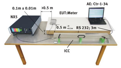
- Ground Reference Plane
- Transient Generator
- Capacitive Coupling Clamp
- Insulating Support
- Grounding Strap/Cable
Ground Reference Plane - Usually made of aluminum, copper, brass or other common metals. Depending upon the application or standard specific metals will be used because of their properties. (i.e. aluminum's malleability, etc.) Typically the same metal(s) will be used throughout many tests for these planes.
Insulating Support - Most commonly polystyrene (Styrofoam), polypropylene or insulating foam-based products are used. When selecting for compliance to a particular standard, reference relative permittivity εr. A table of the permittivity/dialectic constant of common materials can be found at this Website.
Grounding Strap/Cable - These are especially important safety element with this type of testing. They are often included with the generator, however for specific sizing requirements they can be purchased here as well.
Pulse/Waveform Verification
Verifying the waveforms of different EMI pulses from a transient generator is done on a regular basis to ensure it's functioning correctly and that pulses are within specifications. This is typically done by verifying the voltage (open circuit) or current (closed circuit) waveforms. This requires a few different pieces of measurement equipment, however The Conformity Assessment Business has recently come out with Trans-Sense designed for quick pre-check of many common transient pulses.
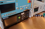
Current Waveform

Combination wave surge current waveforms are verified closed circuit across different CDN Lines. The image on the right shows the verification of L1 to Neutral current waveform using the Haefley Axos 5.
During this verification, no EUT power is used otherwise damage to the measuring equipment will likely occur.
Commonly verification will require a oscilloscope, current monitoring probe (commonly Pearson 110), and an attenuator. Calibrated measurement equipment is often used for ISO 17025 calibrations, however, it may not be required for verification of functionality.
Voltage Waveform

Voltage waveform verification is done using a voltage differential probe comparing to values set values typically provided from a previous calibration. This is done with both combination wave surges, electrical fast transients as well as other voltage based EMI events.
The most commonly used differential probe is the Cal Test CT3681, which provides capabilities for up to 7kV. There are also additional probes on the market place that offer capabilities above 15kV.
Selecting a Transient Generator
Identify Testing Requirements (or attempting to)
Clearly identifying testing requirements is the crucial first step when purchasing (or renting) a transient generator. Without properly identifying what standard or parameters needs to be conducted, finding the correct equipment will be difficult.

While this step seems obvious, it can help avoid a lot of issues down the road. Take the time to determine which testing capabilities are needed and to which level, and what might be needed in the future. Requirements are typically explicitly indicated in the underlying test standard for a given type of product allowing selection of a generator to match those requirements.
Many test systems on the market today have a variety of different configurations allowing for mixing of different capabilities to meet specific customer requirements.
Keep in mind when evaluating, unlike many more common pieces of test equipment,, these pulse generators do not typically offer key code access for additional capabilities.
Coupling Decoupling Networks (CDNs)
Determine Service & Support Needs
Many of the transient test systems on the market today are made overseas and each manufacturer provides different levels of service and support. This can lead to longer than anticipated wait times on inquiries or repairs causing unforeseen issues and testing delays.
While some companies have a lead technician who works almost exclusively with the transient test systems, others may have a variety of engineers involved with running the tests. The number of people and their familiarity with the equipment will be a major factor in determining the potential for user errors.
Regardless of the familiarity with a particular system or manufacturer, systems can malfunction over time leading to even the most technical teams needing repairs and upgrades.
Calibrations
![]()
The two main types of calibrations offered are ISO 17025 and NIST Traceable. There are many calibration labs that offer these capabilities as well as some manufacturers. A manufacturer calibration is an ideal solution for companies who prefer to limit the amount of vendors or want to have the team involved with repairing or manufacturing perform the calibrations.
Many calibration labs also offer onsite calibrations, ensuring that the equipment isn't damaged in shipping while limiting downtime.
Use the same equipment as the test lab
Immunity test systems are commonly used prior to, or following, testing at an accredited EMC testing facility. In many situations, it is best practice to match the equipment the associated test lab as they will be the ones determining if the EUT/DUT passes.

A major benefit of matching the same test system is that it will ensure that any variations in generator tolerances do not impact test results. While this may not seem like a major consideration, it can play a role given some common conducted immunity standards are allow tolerances of +/-10% or greater.
The IEC 61000-4-5 edition 3 combination waveform parameters for the open-circuit voltage tolerance for duration is +/-20% and peak voltage is +/-10%. The associated image indicates, that substantially different waveform parameters would likely still remain “within tolerances” of the standard.
While it isn’t common to see such differences between systems, it is possible to have noticeable differences and is certainly something worth considering when selecting equipment.
Comparing Test Systems
While the designs of the most common systems may look comparable they each offer slightly different capabilities and features. Comparing the test systems on an apples-to-apples basis is a recommended approach for determining what each systems offers.
As we discussed above, many of the systems on the market today are very modular and can be configured to meet customer requirements. This allowsthe customers not to pay for capabilities that they won't need (or anticipate needing).

Transient Generators FAQ
Resources/Additional Information
1) HV Technologies Inc. - Surge Generators & EFT Generators
2) ESD Unlimited - Electrical Fast Transients (EFT)/Burst ESD Details
3) SL Power Electronics - Electrical Fast Transients and Bursts from Power Supply Perspective
4) AC/DC Wire & Supply - Grounding Straps
5) EM Test - Compact NX5 User Manual
6) Engineering ToolBox - Relative Permittivity - The Dialectic Constant
