Electrical Fast Transient (EFT) Test - Overview, Levels, & Setup


EFT Testing
EFT or Burst testing is a conducted immunity test where an EUT is subjected to a series of fast rise time and duration pulses (5ns by 50ns respectively) to ensure compliance and meet product reliability requirements. This EMI event is typically coupled onto power lines through the use of a CDN, but testing can be required on communication, data, and signal lines as well.
What are Electrical Fast Transients (EFT)?
Electrical Fast Transients are a series of quick, high-frequency pulses often caused by arcing. A common cause of power line transients occurs when an AC/DC connection is made or broken, equipment is powered down, or a circuit breaker is switched.
The image below, a switch closing and arcing across, provides an easy-to-understand example of how this type of electromagnetic interference (EMI) can occur. It is most commonly tested in accordance with IEC 61000-4-4 and is also often done to replicate field failures. This standard falls under the basic EMC publication HF conducted disturbances.

The arc associated with switching, is often several arcs and has the potential to vary based upon the distance and breakdown voltage of the air gap.
Where it Occurs
This type of interference has the potential to occur in a large amount of electrical systems and devices. The interconnection of relays to power mains offers many situations for potential arcing and electrical transients. They are commonly tested to and occur in:
- AC Power Mains
- Automotive DC Electrical Systems
- Ethernet & Data Lines
- Electrical Systems & Subsystems(2)
Each electromagnetic (EM) environment has an impact on how this commonly occurring transient materializes and is defined. Given the lower voltage automotive DC systems, EFT in this environment are often considered "microbursts". As an electronics system associated with the occurrence changes, so does how they're defined and tested.
IEC 610000-4-4 Test Requirements
This basic immunity standard is used for testing electrical and electronics system's ability to function given the interference (often called stress) of an EFT event. Immunity is commonly thought of as what interference or noise equipment is able to withstand given the electromagnetic environment in which it functions. These often involve several tests, the most common being combination wave surge, EFT, and electrostatic discharge (ESD) events.
The IEC version has been harmonized with EN 61000-4-4 and under the Electromagnetic Compatibility (EMC) Directive. The most recent version of this standard is the 2012 version and the International Electrotechnical Commission (IEC) offers a Reline version for comparing changes.
Test Levels
The table below, in Texas Instruments IEC 61000-4-x Tests for TI’s Protection Devices provides associated test levels with corresponding line types. The associated test levels, 1-4 are defined by the standard and should be referenced accordingly.

What is the EFT waveform?
The waveform for EFT is defined by a rise time of 5 ns, a pulse width of 50 ns, and a frequency of 5 or 100 kHz.
EFT Burst Waveform

As mentioned above the waveform associated with electrical fast transients are broadly defined by the rise time of 5 ns and pulse duration of 50 ns. These EFT waveforms are generated at a repetition rate of 300ms.
The associated image illustrates the EFT waveform in accordance with IEC 61000-4-4 showing the rise time and duration values.
Frequency
IEC 61000-4-4 allows for testing at both 5 kHz and 100 kHz with the series of bursts being applied every 300 milliseconds. The image below illustrates the burst waveforms at a frequency of both 5 kHz and 100 kHz.

What is the frequency for EFT/Burst?
The frequency for EFT is typically either 100 kHz or 5 kHz, with 5 kHz being the most common. This applies to testing power, ground, as well as signal and control port
Comparing Common Transient Pulses
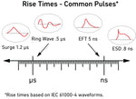
When we take a look at different common transient waveforms certain characteristics come to mind, frequency, voltage and current levels, rise time, duration etc. When we quickly reference different waveforms we commonly use a rise time/duration configuration (e.g. we use 1.2/50 us for surge etc.). The image below illustrates the most common IEC transients based on rise time.

EFT Test Setup
The generic setup for testing to IEC 61000-4-4 for table top equipment can be seen below from the user manual of the EM Test NX5. The guidelines from the associated test standard (as well as safety precautions) should be followed to ensure compliance and accurate results.

Typical test setups will include:
- Ground Reference Plane
- Transient Generator
- CDN (and Clamp if needed)
- Insulating Support
- Connection and Grounding Cables
Ground Reference Plane - Usually made of aluminum, copper, brass or other metal. Often times the same ground plane can be used for IEC 61000-4-2 if EUT sizing requirements are met. Copper and aluminum work excellent for this requirement, are malleable, and commonly referenced in a variety of conducted immunity setups.
Insulating Support - Most commonly polystyrene (Styrofoam), polypropylene or insulating foam-based products are used. When selecting for compliance to a particular standard, reference relative permittivity εr. A table of the permittivity/dialectic constant of common materials can be found at this Website.
Grounding Strap/Cable - These are especially important given safety with this type of testing. They are often included with the generator, however for specific sizing requirements they can be purchased here as well.
EFT/Burst Test Equipment
Below is a brief overview of equipment commonly used for immunity testing for to IEC 61000-4-4. Typically for testing data lines a capacitive coupling clamp is used, whereas power lines are tested using a CDN.
- Transient Generator
- Coupling Decoupling Networks (CDNs)
- Capacitive Clamps
- Verification Equipment (if required)
EFT Generators
Transient immunity test systems designed for electrical fast transient testing are also typically paired with testing capabilities for combination wave surges for IEC 61000-4-5. The associated video provides an overview of the EMC Partner IMU-MGS as well as the CN-EFT1000 capacitive coupling clamp.
What are EFT Generators?
Electrical fast transient or burst generators provide the series of fast rise time and duration (5 μs/50 μs) pulses for immunity testing to IEC 61000-4-4.
Power Line Coupling
The power requirements of the equipment under test will determine if the coupling decoupling network (CDN) built in the transient generator will be sufficient or if an external one will be required. Today most transient generators allow for testing equipment up to ~ 300 Volts and 16 Amps without the need for an external CDN.
External power line CDNs designed for EFT testing are commonly manufactured stand-alone at higher voltage and current levels but are often combined with surge capabilities at the 480 Volts 32 Amps threshold. If there is no communication with the transient transient generator then the CDN can typically be used with most common test systems. This is not the case for wave surge testing to IEC 61000-4-5 line synchronization communication is required.
The associated video focuses on the EM Test PCD 8 B-3-690-1000-100 EFT CDN capable allowing for testing line up to 100 Amps. It is crucial when setting up a manual CDN that a solid connection is made and correct gauge wire is used.
Data/Communication Line Coupling
Coupling electrical fast transients onto data or communications lines is typically done with a capacitive coupling clamp. These devices are designed in accordance with IEC 61000-4-4 and can be purchased after the generator if needed.
Most coupling clamps can be used with a variety of generators given that the proper connection to the generator is provided.
The below test setup diagram provided by the user manual of the Teseq CDN 3425 provides an excellent overview of a test setup using a capacitive clamp.

Given the quick risetimes and voltages associated with burst testing, grounding is especially important. The majority of generators and systems offer grounding cables ensuring that proper connection and paths are maintained. When referencing setup requirements, spacing can play an important consideration given the potential for arcing.
How to use an EFT Generator
While transient generators design can vary by manufacturer, most include EFT to at least 4.4 kV, a burst/EFT out connection, coupling decoupling network (CDN), as well as an interface to modify testing criteria. For most testing the front panel is used to change testing criteria, however for more specialized routines software is used.
The video for EFT/burst testing with the Haefely Axos 5 includes:
- Connections to the front and back of unit
- Methods for Connecting to EUT/DUT
- Capacitive coupling clamp Connection
- Modifying testing criteria & levels
- System interface and CDN
Testing using a CDN
The two methods for power on EFT testing are from the direct out with a capacitive coupling clamp, or through the CDN for power ports. The connections for the EUT supply input are typically located on the back of the generators with the front side connections providing output to EUT through the CDN.

You will notice from the image on the right, the connections for the CDN are separated by line instead of the more common NEMA style plugs. This allows for both AC and DC testing and can require plugs to be made to allow for connection to common low-voltage local mains power.
The EUT supply voltage and current levels can be changed by using a power supply in lieu of local power mains. The voltage and current limitations of coupling decoupling networks determine what the max voltage and current they are able to operate at. While external CDNs can allow for EUTs upwards of 200 Amps, most built-in networks typically have a limit of 16 Amps with varying voltage levels.
How to Verify EFT Waveforms
While formal ISO 17025 calibrations are typically done on an annual basis, it is best practice to verify that the transient generators are operational on a more regular basis. The below video provides a brief overview of how to conduct a basic verification of electrical fast transient pulses ensuring the generator is functioning correctly.
The video for EFT pulse verification with the EM Text Compact NX5 includes:
- Modifying test criteria on display for verification
- Verification both through CDN and Burst out
- EFT pulses through 50 Ohm adapter
- Evaluation of pulse width, duration, and max value
EFT/Burst Testing FAQ
Electrical Fast Transient testing is a conducted immunity test designed to subject an EUT to a series of fast rise time and duration pulses to ensure compliance and meet product reliability requirements.
Within EMC EFT is a conducted immunity test designed to simulate a series of fast pulses, commonly called bursts, to evaluate the impact on the function of the EUT.
The EFT immunity tests purpose is to ensure products are designed rugged enough to withstand fast transients commonly caused when an AC/DC connection is made or broken, equipment powered down, or circuit breakers switched.
References:
Another EMC resource from EMC Standards. (n.d.). Retrieved January 24, 2025, from https://www.emcstandards.co.uk/files/61000-4-4_immunity_to_fast_transient_bursts.pdf
Application Report IEC 61000-4-x Tests for TI’s Protection Devices. (2015).
https://www.ti.com/lit/an/slva711/slva711.pdf?&ts=1590083707807
Electrical Fast Transients (EFT)/Burst ESD Details. (2019). Esdunlimited.com. https://www.esdunlimited.com/eft.html
IEC 61000-4-4:2012 RLV. (2025). Webstore.iec.ch. https://webstore.iec.ch/en/publication/22271
IEC Transient Pulse Immunity | IEC 61000-4-4 EFT/Burst Testing. (2019). Ametek-Cts.com. https://www.ametek-cts.com/know-how/iec-transient-pulse-immunity/iec61000-4-4-eft
Standard Surge Waveforms. (n.d.). Www.pscad.com. https://www.pscad.com/webhelp/Master_Library_Models/CSMF/Surge_Generators/Wavelet_Transformation_(WT).htm


