Electromagnetic (EM) Clamps Overview & Testing
Electromagnetic (EM) Clamps
EM Clamps are injection devices, commonly designed around IEC 61000-4-6 requirements, that provide immunity testing to conducted RF disturbances. As with the current clamp injection method that uses a bulk current injection probe, it is not the preferred method which is illustrated in Figure 12. Annex A of IEC 61000-4-6:2013 focuses on the EM and decoupling clamps and includes design and characterization requirements. CDN's are the preferred method when available.
What are Electromagnetic (EM) Clamps?
EM clamps are RF current injection clamps that have both inductive and capacitive coupling allowing for induction on cables in the frequency range of .15 MHz to 1000 MHz. The electromagnetic designation (EM) comes from the fact that this clamp uses both inductive and capacitive coupling simultaneously.
The related video provides an overview of EM Clamps, it includes:
- Typical Specifications of EM Clamps
- EM Clamps & Related Accessories
- Test Level Setting Calibration Setup
- Test Level Setup Overview
Construction of the Clamp
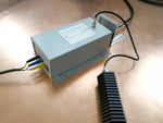
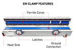
EM clamps are made of two series of ferrite ring cores connected by a hinge that allows for cables to be placed between the openings. Along with the device containing ferrite there is a also a metal cable/rod allowing for connection during calibration as well as verification of the clamp's characteristics.
The associated image of the EM Test EM101 illustrates the major components of the clamp including the ferrite on both sections. Later sections will focus in more detail on the setup for both test level calibration and the test itself.
Within Annex A of IEC 61000-4-6 typical specifications for EM Clamp are provided including the length, opening diameter, as well as other requirements. These requirements include requirements for electrical characteristics of the clamp including impedance and coupling factor.
Advantages of the EM Clamp
Electromagnetic clamps offer advantages for testing over other methods depending on the requirements of the test:
- Ability to test cable bundles
- High frequency capabilities
- No limitations on cable types
- Very Efficient Coupling
Features of EM Clamps
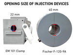
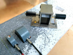
The design and features of the EM Clamp lends itself well to certain types of tests, especially those in accordance with IEC 61000-4-6 where bundles of cables need to be tested. If using the CDN method multiple CDNs would be required for each cable type which may not be readily available to meet the testing timeline. Much like the bulk current injection (BCI) probe the clamp method offers flexibility on the type of cables that the test can be conducted on, however, it is not as efficient as a CDN. Another consideration is the limited clamp opening diameter which substantially limits the size of the cables that can be tested. The associated image illustrates the difference in opening sizes between the EM Test EM101 clamp.
Frequency Range
Typical electromagnetic clamps on the market provide a useable frequency range from 10 kHz to 1 GHz making it an ideal solution for both compliant testing to IEC 61000-4-6 as well as pre-compliance tests. A comparison of the typical frequency ranges along with the injection equipment is provided below. Less common variations of injection equipment do exist which offer different frequency range capabilities, however the information below is what is most common.
- Coupling Decoupling Network (CDN) - 150 kHz to 300 MHz
- Electromagnetic (EM) Clamp - 10 kHz to 1 GHz
- Bulk Current Injection (BCI) Probe - 10 kHz to 400 MHz
Power Limitations
The power handling capabilities of EM Clamps generally decrease as the frequency increases. Many of the most common clamps including the Teseq KEMZ 801B and Com-Power CLEM-6146 clamps can handle double the power level at the 10 kHz to 100 MHz range at what they can at the higher range of 230 MHz to 1 GHz.
Ferrite Cores & Clamp Length
As mentioned in prior sections, Annex A provides a variety of different EM clamp specifications, including the clamp length and ferrite core requirements. The length of 650 mm +/-50mm is explicitly stated and requires a substantial amount of cabling in order to accommodate the sizing requirements. The amount and sizing of the ferrite cores is also indicated in Annex A of IEC 61000-4-6.
Setup of the EM Clamp
Electromagnetic clamps are most commonly used for conducted RF immunity testing in accordance with IEC 61000-4-6. The test setup is first calibrated and test levels are recorded and then the test itself is conducted based upon saved test levels. As with other test methods in IEC 61000-4-6, 150 Ohm to 50 Ohm adapters are used during the calibration.
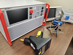
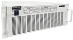
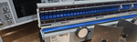
The associated image is a typical calibration test setup in accordance with IEC 61000-4-6. In the image the required test equipment is combined into a single test system, the Teseq NSG 4070. As with other immunity tests grounding is especially important, it crucial that calibration adapters have a good connection with the ground reference plane or the calibration will fail.
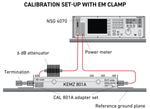
When acquiring an EM Clamp either by purchase or rental, it is important to get the 150 Ohm to 50 Ohm that correspond with model of the clamp. Typically these adapters and with the correct connectors are packaged together in a kit (as with Teseq CAL 801A designed for the Teseq KEMZ).
It is important that the 6 dB attenuator is added to the output of the amplifier or conducted RF test system, otherwise damage can occur to the power meter!
Test Setup
Once the calibration has been run successfully, the setup will be adjusted for conducted testing where the saved levels will be applied. This setup, as seen on the right, still has the 6 dB attenuator output and doesn't include a monitoring probe or decoupling clamp. When conducting the actual test, the calibration adapters are removed from the setup.
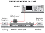
The purpose of a ferrite decoupling clamp is to prevent the test signals applied to the intended cables from impacting other devices, equipment, or systems, that are not under test. They also improve the reproducibility of results. These devices are commonly used when there are multiple lines connected to the EUT that shouldn't be exposed to the inference.
Conducting Testing
Conducted RF testing to IEC 61000-4-6 using the EM clamp method is done in very much the same way as that of a CDN, saved power levels provided during the calibration are applied to the EUT. Given the amount of data that is needed during the test level calibration, it is recommended that software is used to help expedite testing.
The associated video provides information on the EM 101 clamp including an overview, running a calibration, and the test setup. The video includes:
- Capabilities of EM 101 Clamp
- Test Level Calibration & Setup
- Completing Level Calibration
- Test Setup using NSG 4070
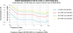
Power Levels
As mentioned above, testing applies the saved forward power levels using a substitution method. These levels will be determined by the electrical characteristics of the clamp itself (coupling factor etc.) and impacted by the attenuator as well as cable loss. The below graph illustrates the power requirements for different test levels over the frequency range according to IEC 61000-4-6.
Troubleshooting
While there are many potential problems that plague conducted RF test setups, there are a few that seem more common with EM Clamps. Unlike other injection equipment, the amount of ferrite cores increase the probability for damage.
Poor Ground Connection
With conducted RF testing, good ground connections to the reference plane are crucial. During the calibration a metal rod is placed through the clamp which then connects to the calibration adapter allowing for associated levels to be determined. Different components commonly get slightly bent or worn over time, the grounding connections on these no longer may provide a physical connection without a bolt or an adhesive.
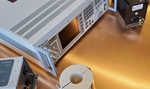
In the associated image copper tape is used to ensure that the calibration fixture maintains a good connection with the ground reference plane. Conductive tape is ideal when holes cannot be drilled in the reference plane, this is especially true when harder metals are used for the reference plane.
Broken/Cracked Ferrite
The many ferrite cores on both sides of the clamp can break or crack causing issues during the calibration and testing. The ferrite is fairly brittle and it is important that care is given when opening and closing the clamp as well as transporting it. Many clamps on the market today include a padding material between the top and bottom sections for transport or when not in operation, helping to limit the chance of damage to the ferrite. The damage to the ferrite can be seen visually or found with the a Network Analyzer.
Bad Attenuators
During both the calibration and testing a 6dB attenuator is connected from the amplifier output on the test system. Attenuators are typically fairly rugged, however depending on the model can have set input and outputs connections. If the attenuator is used in reverse damage can occur to the attenuator rending it unusable.
EM Clamp FAQ
Typically the frequency od Electromagnetic Clamps are from 10 kHz to 1 GHz with some models providing a usable frequency range of 150 kHz to 1 GHz.
EM Clamps are used for conducted RF immunity testing in accordance with IEC 61000-4-6.
References:
Adamczyk, B. (2017, September). Current Probe Measurements in EMC Testing - In Compliance Magazine. In Compliance Magazine. https://incompliancemag.com/current-probe-measurements-in-emc-testing/
AMETEK CTS | NSG 4070C1. (2019). Ametek-Cts.com. https://www.ametek-cts.com/products/brands/teseq/nsg-4070c1
Application. (2025).Current Probe For Emissions Measurement | Com-Power Corporation. Com-Power.com. https://www.com-power.com/products/current-probes/emissions-current-probes/clce-400
Mee, S. (2018, June). Bulk Current Injection (BCI) – Substitution Method and Closed-Loop Method with Power Limitation - In Compliance Magazine. In Compliance Magazine. https://incompliancemag.com/bulk-current-injection-bci-substitution-method-and-closed-loop-method-with-power-limitation/
Samuels, T. (2023). Bulk Current Injection Testing. Ahsystems.com. https://www.ahsystems.com/notes/bulk-current-injection-test.php