Bulk Current Injection (BCI) Test - Equipment, Methods, & Setup
Bulk Current Injection
The BCI test is a continuous RF immunity test designed to ensure both compliance and product reliability when exposed to conducted EMI disturbances coupled with an injection probe. This immunity test is commonly done in commercial, military, and automotive applications with varying test levels, frequencies, and requirements.
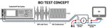
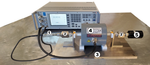
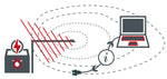
The above image illustrates the concepts of the test using a current monitoring probe common in both the closed loop and substitution methods. This conducted RF immunity test is commonly conducted from as low as 4 kHz to 400 MHz with some requirements going higher in frequency.
What is bulk current injection (BCI)?
Bulk current injection is a conducted RF immunity test that injects a modulated signal using a current injection probe onto cables in an effort to replicate EMI stress in the anticipated environment which the equipment will operate.
BCI Testing
Regardless of if the substitution or closed loop method is used, the calibration of setup is the first step. During this process the associated test levels and corresponding power levels are saved to be used later while conducting the test.
The video shows the current clamp calibration setup according to IEC 61000-4-6 using the Teseq NSG 4070 test system.
It provides an excellent overview on:
- Setup of RF Injection Equipment
- Calibration Process to Test Levels
- Using Front Panel Software
- Modifying Testing Parameters
How BCI is measured
Bulk current injection is measured a few different ways depending upon the underlying standard and method. For commercial applications, volts are used which are associated with a set energy level during the calibration. For some automotive and military applications current measurements on associated cabling during feedback loop are used typically in mA or dBuA.
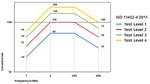
Many test level requirements are based upon a series of values over a given frequency, often called a curve. The test levels on the left for ISO 11452-4:2011 provide an excellent reference guide for the associated levels over the required frequency range.
Typically these levels are preprogrammed into the software or system allowing for testing to be conducted efficiently. The RF power amplifier, as well as other associated equipment, will determine what levels can be met and over what frequencies.
Test Methods
The first step before conducting BCI testing is to run a system calibration. Following the calibration, testing will focus on the associated method along with any standard or specific test requirements.
Prior to running any test, including the calibration, proper attenuation and safety considerations must be followed! While many systems are designed with over-testing protection, if proper connections and procedures aren't followed damage to equipment can occur.
System Calibration
The calibration of the setup or system including the current injection probe is done prior to running the test. During this calibration process if there are any issues with the setup or equipment it will impact the results, often times not completing the test.
What is the system calibration for BCI?
The system/setup calibration for Bulk Current Injection (BCI) testing is the process of determining and storing the power requirements needed to meet selected test levels over the required frequency range.
During the calibration process the associated test information will be entered including test level, frequency, coupling device, as well as other equipment considerations. Typically the calibration is not done modulated, however all other criteria will be entered for testing as if testing will be conducted.
The below example of calibration setup for IEC 61000-4-6 includes:
- 20 dB Attenuator
- 150 Ohm to 50 Ohm Adapters
- Fischer FCC-BCICF-6-150 Fixture
- Fischer F-120-9A Probe
- 50 Ohm Termination Load
RF Signal Modulation
The two methods of modulation used for signals during the BCI test are amplitude modulation (AM) and amplitude modulation peak conservation (AM PC). The AM PC signal method is common in automotive applications where the peak of the modulation is at the same level as the peak of the CW signal.
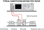
What is the substitution method for BCI testing?
The substitution method for BCI testing uses the recorded/set power levels provided during calibration as the main factor for testing and can limit the current depending upon EUT line impedance.
Substitution Method
During the calibration process the system will evaluate and adjust what power is needed to induce set current levels with a 50 Ohm impedance over the frequency range. This same power level associated with the 50 Ohm impedance will then be used during testing the EUT/DUT, essentially switching out the calibration fixture for the equipment under test.
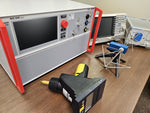
The image shows a typical test setup using the substitution test method. You will notice that a current monitoring probe can be used depending on the test standard. The probe is typically used to verify levels or limit the current, depending on the source impedance.
Common Test Standards Include: IEC 61000-4-6, ISO 11452-4, & MIL-STD-461 CS114
What is the closed loop method for BCI testing?
The closed loop method (also called a leveling loop) uses a current monitoring probe to measure current levels and make adjustments to the RF power to meet a set current threshold on the associated cables.
Closed Loop Method
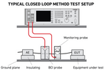
The closed loop method is focused on set current levels using power estimates from the calibration process with adjustments made from measurements of the current monitoring probe (commonly in mA or dBµA). The power adjustment is made within a tolerance to ensure that there is a limit on the power needed as DUT/EUT with higher impedance have the potential to require substantially more power.
The image shows a common test setup where the current monitoring probe is used to monitor levels going towards DUT/EUT and adjustments made using the RF test system.
Common Test Standards Include: ISO 11452-4, Ford FMC1278, & RTCA/DO-160 CS Test
Pre-compliance & Troubleshooting Failures
Radiated immunity testing is expensive and often long periods for product modifications at a test facility are costly. For some testing, particularly at lower frequency ranges, a BCI test can replicate similar impacts and results on the EUT/DUT.
The comparable test levels presented in commercial radiated immunity tests can also be seen in conducted immunity testing (as with 10V/m and 10V). This lends itself well for conducted RF testing to be used for troubleshooting radiated EUT/DUT failures at significantly lower costs. The two largest considerations for this type of testing will be the frequency of concern and source impedance.
This method is best used at lower frequencies during radiated testing where coupling is likely occurring onto cables going towards the EUT/DUT.
Common Standards
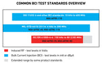
The three most common requirements for conducted RF immunity are IEC 61000-4-6, ISO 11452-4, as well as MIL-STD-461G CS114. While each standard has unique methodologies and requirements all have equipment crossover and replicate similar events. The below image shows the most common standards, the associated frequencies, as well as a bit about the criteria for each.
Application Guides/Notes
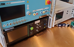
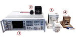
The setup of the equipment is crucial for BCI testing, below you will find application notes providing a guide for test levels and setups using the Teseq NSG 4070 system.
IEC 610000-4-6 Application Note
BCI Test Equipment
Bulk current injection (BCI) equipment can vary by testing requirements, however typically includes:
- Conducted RF Test System
- Associated Attenuators & Loads
- BCI Injection Probe & Calibration Fixture
- Current Monitoring Probe & Calibration Fixture
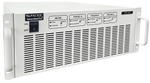
Conducted RF Test Systems
Conducted RF systems provide many of the commonly required equipment in a single, easy to use system that allows for effective testing. These systems can be configured with different capabilities, it is important to ensure that system is capable of meeting associated testing requirements.
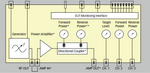
The block diagram above of the Teseq NSG 4070 shows the different components inside the RF test equipment. These systems typically include:
- RF Signal Generator
- Power Meters or Spectrum Analyzer
- RF Power Amplifier
- Interface & Software
RF Power Amplifiers
The RF power amplifier, along with the other associated equipment, determines the test level and frequency limitations. The amplifiers used for BCI testing can go as high as 260 watts, with 110 Watts often needed for higher test levels in automotive and commercial requirements. The most common RF amplifiers include:
At lower power levels amplifiers are often built into the test systems and at higher levels tend to be external. When using an external amplifier a dual directional coupler is needed for forward and reverse power measurements typically run through the RF system. When testing at higher levels it is crucial that proper attenuation is used to help protect the power meters or analyzer.
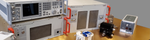
The use of a dual directional coupler with an external amplifier provides additional setup connections and considerations. The video to the right provides a guide for adding an external amplifier to an RF system and includes:
- Connecting External RF Power Amplifier
- Using Dual Directional Coupler & Importing Data
- Running System Calibration
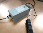
What is a Bulk Current Injection (BCI) Probe?
Bulk current injection probes, also called BCI probes, are circular windowed devices that inductively couple RF current onto wires or cable bundles used in immunity testing.
Bulk Current Injection Probes
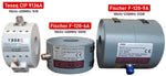
BCI probes are generally categorized by transfer impedance, frequency range, power handling, as well as compliance to a particular standard. The image below shows three of the most common BCI probes including power rating and frequency range:
The calibration fixture provides a stable impedance during the system calibration. Using the clamp on hinge the probe is opened and secured around the fixture then connected to the RF system. The calibration fixtures are designed to be used with a particular model of probes and are not interchangeable.
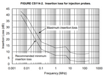
The graph on the right from MIL-STD-461 CS114 provides the limitation on the insertion loss for injection (BCI) probes. The associated standards limitations should be referenced and compared to the probes' capabilities prior to testing.
What are RF Current Monitoring Probes?
RF current monitoring probes are circular, windowed devices used for measuring RF currents on cables or wires without direct electrical contact.
RF Current Monitoring Probes
Current probes vary in their sensitivity, power handling, and frequency range. For bulk current injection testing we are mainly concerned with RF measurements from 10 kHz to 400 Mhz. Current monitoring probes are commonly used in RF immunity applications for measurements of RF levels injected on the associated cabling after the injection probe.
Additional in depth information on current probes and how they are used in EMC testing, can be found here.
BCI testing standards and requirements will determine which probes are best suited to meet testing needs. The monitoring probe(s) should cover the entire test frequency range.
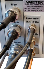
It is also important that the calibration fixtures be ordered with the probe as they can be needed for testing and ISO 17025 calibration of the monitoring probe. The image on the right shows the Teseq MD 4070A in the calibration fixture.
Software
Given the wide frequency range and large number of data points typical in conducted RF testing and the calibration process, the EMC/EMI software is a crucial component. This can be done by using the front panel of a conducted RF system, or controlling the entire system via a laptop with a computer application. Should stand alone components (signal generator, spectrum analyzer, etc.) be used, the associated drivers must be available for the software to allow for communication between components.
Troubleshooting BCI Test Setup
1. Check Connections
The first step in determining why the system setup isn't operating properly is to check the connections between the different components of the setup. It is especially important if using an external amplifier with a dual directional coupler where there are substantially more connections which can be switched.
While reviewing the connections, also check to ensure that the the RF connectors are threaded properly. Depending upon the age and wear of the connectors it can be difficult to tell if the connector is threaded correctly. This can be done by hand tightening each connection ensuring good connections are made.
2. Verify Attenuator Functionality
RF Attenuators tend to be pretty rugged, however overpowering and shipping damage can occur. Should an attenuator no longer work, the test system will be unable to run a calibration at any level. When the connections are being checked it is best practice to replace each attenuator individually and attempt to run the calibration to determine which is no longer functioning.
Attenuators can also be verified prior to putting them in the setup eliminating them as a possible culprit. This can be done using a power meter and sensor to verify the correct attenuation.
3. Check Software
EMC/EMI software and the user interface for test systems are often flexible enough to provide solutions to a variety of BCI requirements. Many issues can arise from unfamiliarity with software, this is especially true with complex test methods and setups.
A simple error when entering data or selecting criteria can cause the entire setup to fail. It is best practice to verify criteria before performing a test method for the first time. Referencing the user manual or resources to verify criteria can help resolve software issues.
4. RF Amplifier Evaluation
The RF power amplifier can be one of the most fragile components of a conducted RF test setup. The durability of the amplifiers will vary by manufacturer, but amplifiers should be evaluated on a regular basis to ensure they're functioning correctly.
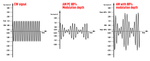
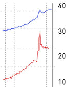
Should the issue arise from the amplifier it's possible spikes in power measurements could be noticed. An example of this is shown on the left image where the amplifier failed above 150mA. Depending upon the damage, the amplifier may fail to meet certain test levels or stop at a set frequency.
Bulk Current Injection FAQ
Bulk current injection (BCI) is an EMC conducted RF immunity test method designed to expose EUT/DUT to EMI to ensure compliance and product reliability requirements.
Bulk current injection testing is a conducted RF test where a bulk current (BCI) probe is used to induce EMI stress onto cables of a EUT in an effort to ensure immunity to EMI.
References:
Adamczyk, B. (2017, September). Current Probe Measurements in EMC Testing - In Compliance Magazine. In Compliance Magazine. https://incompliancemag.com/current-probe-measurements-in-emc-testing/
AMETEK CTS | NSG 4070C1. (2019). Ametek-Cts.com. https://www.ametek-cts.com/products/brands/teseq/nsg-4070c1
Application. (2025).Current Probe For Emissions Measurement | Com-Power Corporation. Com-Power.com. https://www.com-power.com/products/current-probes/emissions-current-probes/clce-400
Mee, S. (2018, June). Bulk Current Injection (BCI) – Substitution Method and Closed-Loop Method with Power Limitation - In Compliance Magazine. In Compliance Magazine. https://incompliancemag.com/bulk-current-injection-bci-substitution-method-and-closed-loop-method-with-power-limitation/
Samuels, T. (2023). Bulk Current Injection Testing. Ahsystems.com. https://www.ahsystems.com/notes/bulk-current-injection-test.php