Conducted RF Immunity Testing - Overview, Methods, & Equipment

Conducted RF & Immunity Testing
Unlike radiated RF, conducted RF is focused on coupling and exposure via connected lines or cables. Both capacitive and inductive coupling methods have the potential to provide transmissions of noise onto associated cables providing a path towards the electronic or electrical devices.[1]

The levels of interference traveling down these conducted cabling paths will vary in strength in relation to the field that they are exposed to. The greater the electric or magnetic (E and H) fields [2], the higher the level of RF noise that can be expected traveling along the associated cabling.
What is Conducted RF?
Conducted RF are radio frequency spectrum signals and energy transmitted though capacitive and inductive coupling onto different lines and cablingincluding power and data.
Conducted RF Immunity Testing
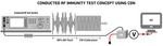
Immunity testing to conducted RF noise or interface attempts to replicate the same environmental stress by using different injection and testing methods. The below image illustrates the concepts of the test using the substitution method with a coupling decoupling network (CDN) commonly done to IEC 61000-4-6.
What is Conducted RF Immunity Testing?
Conducted RF Immunity testing is an EMC test where the EUT is subjected to verifying levels of radio frequency EMI stress through exposure through cabling to determine any impact on the function.
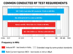
Conducted RF immunity testing is a continuous EMC test commonly required for commercial, automotive, and military equipment or products. Testing requirements, frequency range, setup, as well as the required test equipment will vary by standard and test level.
The image to the left provides a reference for some of the most common requirements including their associated frequency ranges. While some automotive and military testing can span a much larger frequency range, 150 kHz to 230 MHz is the most common.
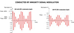
Signal Modulation
As shown above a modulated RF signal is used for conducted RF testing immunity testing. This is typically a 1 kHz sine wave with an 80% amplitude modulation (AM) with peak conversation (PC) typically used during bulk current injection testing. For commercial testing the calibration is done CW and then the AM signal is applied during testing. The below image illustrates the different modulations typically used in this immunity tests.
Application Guides/Notes
The below application guides using the Teseq NSG 4070 test system provides information on the common test requirements and setup.
IEC 610000-4-6 Application Note
IEC 61000-4-6 Testing
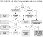
IEC 61000-4-6 allows for three different injection methods, coupling decoupling network (CDNs), electromagnetic (EM) clamp, current injection, and direct injection. The preferred method is using a CDN which are designed for testing specific cable types. Depending on the equipment under test this could involve using multiple CDNs if multiple ports/connections need to be tested. The below image provided by the Teseq CDN selection guide, provides the rules for selecting the injection method.
Test Levels - Substitution Method
IEC 61000-4-6 uses the substitution method for testing (with all injection methods) where the voltage level of the calibration data over the given frequency is applied to the EUT. The calibration setup for this standard specifies an 150 Ohm source impedance and uses the associated levels to conduct testing.
The test level requirements for this standard, regardless of injection method are:
- Test Level 1 - 1V r.m.s.
- Test Level 2 - 3V r.m.s.
- Test Level 3 - 10V r.m.s.
- Test Level X - Special (unspecified)[1]
Conducting Testing
Regardless of the injection method used, the calibration of test setup is the first step. During this process the associated test levels and corresponding power levels are saved to be used later while conducting the test. The below image illustrates the calibration and test setup of the NSG 4070 for IEC 61000-4-6 testing.
CDN Injection Method
Coupling Decoupling Networks (CDNs) are the preferred injection method of IEC 61000-4-6 as seen above from the selection rules. They provide repeatable, accurate results while ensuring auxiliary equipment is protected. CDNs also have the benefit of being the most efficient method for injection allowing lower power RF amplifiers to be used.
What are Coupling Decoupling Network (CDNs)?
CDNs are devices that allow for injection RF disturbances on cables towards the EUT and subsequently removing them prior to auxiliary equipment while providing 150 Ohm impedance.
Types of CDNs
These networks are designed specifically for a particular port or cable type (power, communication, etc.). This has the potential to lead to multiple CDNs required for testing depending upon the test plan and ports tested. The most common CDN types include:
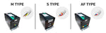
CDN-S1 - Screened Cables
CDN-M1/-M2/-M3 - Unscreened Supply (Mains) Lines
CDN AF2 & AF8 - Unscreened Unbalanced Lines
CDN T2, T4, & T8 - Unscreened Balanced Pairs
The vast number of coupling decoupling networks available relate to the variety of different cables and ports tested. Teseq, a manufacturer of EMC equipment, provides an excellent guide that goes into great detail on the variety of CDNs available. The guide can be accessed by clicking here.
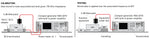
CDN Setup & Calibration
The calibration setup for IEC 61000-4-6 using the CDN injection method can be seen to the left using the Teseq NSG 4070 and EM Test CDN. It includes:
1) Conducted RF Test System (NSG 4070)
2) 100Ω Adapters
3) 6 dB Attenuator
4) Coupling Decoupling Network (CDN)
5) 50 Ω Termination Load
Direct Injection
This method requires a physical connection from the RF generator to the cabling of the device or equipment under test. This can involve some work as it is required to make manual connections including splitting the EUT cabling. This method when used for IEC 61000-4-6 also requires capacitors and resistors put in place between the connection.
Electromagnetic Clamp Injection Method
What are Electromagnetic (EM) Clamps?
EM clamps are hinged enclosures that use split-core ferrites to inject disturbance signals through a combination of inductive and capacitive coupling towards the EUT.
EM Clamps are typically used when CDNs aren't applicable as a more suitable option. The clamps themselves are made of ferrite as well as conductor and insulating plates providing a combination of inductive and capacitive coupling. The ferrite used in construction of the clamp must be in good condition, both on the top and bottom, for the equipment to be functional.
The EM Clamps provide an excellent option when longer EUT cable lengths are available as they're more efficient allowing for less power to be used.
It is important to consider the cable length available and thickness of the cables or bundles when using EM clamps. Most clamps have a length between 58 inchs and 70 inchs and can handle a max diameter cable or bundle of 20mm.
EM Clamp Setup
The setup for using EM Clamps is especially important given the importance of grounding has on conducted RF immunity testing. The image below illustrates the calibration setup using the NSG 4070 test system.
1) Conducted RF Test System (NSG 4070)
2) CAL 801A 100Ω Adapters
3) 6 dB Attenuator
4) EM Test EM101 Clamp
5) 50 Ω Termination Load
6) Calibration Cable
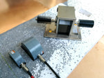
Current Clamp / BCI Injection Method
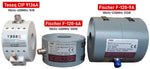
The bulk current injection method is commonly required for many military and automotive applications and can use the substitution method for injection. The component that induces the associated RF onto the cable(s) is the current injection probe (CIP). These probes use split ferrite pieces with a clamping mechanism as way of injecting required current levels onto cables and associated connected devices.
A major benefit of using this method is having a sizable window or opening on the injection probe, typically 43 mm and a clamping feature. This is ideal for situations where RF testing is required on bundles of cables, where otherwise testing would be substantially more difficult. This is also an easier solution when cabling cannot be cut, because the clamp can be opened and closed around the wires/cables.
This method is measured in either mA or dBµA with a current monitoring probe during calibration processes. Typical frequency ranges start at around 4 kHz to 400 MHz with some automotive requirements going into the Gigahertz range. This test typically requires the most power to drive enough RF though the injection probe, often requiring external power amplifiers mentioned above.
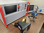
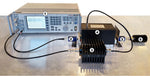
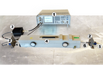
BCI Test Setup
The associated video walks through a BCI test setup where an external amplifier is used and a calibration is run. The video Teseq NSG 4070 conducted RF test system with the Teseq CBA 400M-260 as well as the Teseq CIP 9136A injection probe shown above.
- Setup of RF Injection Equipment
- Calibration Process to Test Levels
- Using Front Panel Software
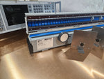
Conducted RF Test Systems
Conducted RF systems provide many of the commonly required equipment in a single, easy to use system that allows for effective testing. These systems can be configured with different capabilities, it is important to ensure that system is capable of meeting associated testing requirements.
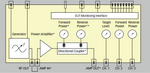
The block diagram above of the Teseq NSG 4070 shows the different components inside the RF test equipment. These systems typically include:
- RF Signal Generator
- Power Meters or Spectrum Analyzer
- RF Power Amplifier
- Interface & Software
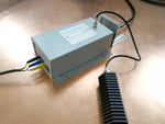
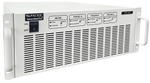
RF Power Amplifiers
The RF power amplifier, along with the other injection equipment, determines the test level and frequency limitations. The amplifiers used for BCI testing can go as high as 260 watts, with 110 Watts often needed for higher test levels in automotive and commercial requirements.
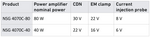
The efficiency of the injection method plays a large role in the power of the amplifier that is needed to meet the desired levels. With BCI more power is needed, where as with CDNs that are more efficient desired levels can be reached with less power. The image on the right illustrates the different injection methods and anticipated test using the same power.
Signal Generator
The signal generator used in testing can either be built into the test system or can be external. Given that testing is conducted with a 1 kHz 80% AM sine wave it's necessary that the signal generator have the capabilities for modulation. This is typically ordered as an option if not integrated within a conducted RF test system.
Conducted RF Immunity FAQ
The conducted RF test is an EMC immunity test where equipment is subjected to radio frequency disturbances through injection on power or data lines.
Conducted RF immunity is when EUT/DUT are able to withstand when radio frequency EMI is injected at set levels on associated cabling going to the equipment or device.
References:
[1] Helping you solve your EMC problems Another EMC resource from EMC Standards A Practical Guide for EN 61000-4-6: Testing and measurement techniques. (n.d.). https://www.emcstandards.co.uk/files/61000-4-6_immunity_to_conducted_rfi_2_1.pdf
[2]Conducted RF Testing – Atlas Compliance & Engineering. (2020). Atlasce.com. https://atlasce.com/services/immunity-testing/conducted-rf-testing/
[3]What is RFI (EMI) / EMC? - Fuseco. (n.d.). Www.fuseco.com.au. https://www.fuseco.com.au/articles/what-is-rfi-emi-emc
Milne, A. (n.d.). Common Sources of Interference. Www.rfvenue.com. https://www.rfvenue.com/blog/2014/12/14/common-sources-of-interference
RF Immunity Testing a handy guide. (n.d.). Retrieved February 11, 2025, from http://www.unitest.com/pdf/RF_immunity_testing_e_3.pdf
Teseq. (2019). Teseq.com. https://www.teseq.com/applications/induced-rf-i.php