ISO 7637-3 - Transient Injection Methods & Equipment
Transients Testing Data/IO lines
Automotive transient immunity testing is done on a variety of different types of cables including data or communication lines (and to the subsequent ports). This can be done on individual lines, or to bundles with multiple different lines. Certain test methods lend themselves better to each type. ISO 7637-3 includes three methods and applies to 12 volt or 24 volt electrical systems with severity levels and status classification and other criteria from ISO 7637-1.
The pulses that are injected are based off ISO 7637-2 pulses 2a (positive and negative) which are the slow pulses and pulses 3a and 3b considered fast pulses. Test pulses 3a & 3b have fast risetimes in the nanosecond range while pulse 2a has a slower microsecond rise time.
Regardless of the injection method used, waveform verification and level adjustment (if needed) is required prior to conducting testing. This helps to ensure that the correct waveforms and levels are making it onto the associated cabling given the potential for loss.
The associated video on ISO 7637-3 focuses on the equipment needed for both the CCC and ICC methods. The video includes:
- Teseq and EM Test Equipment for ICC & CCC
- Calibration/Level Setting Setups
- ISO 7637-3 Testing with the EM Test UCS 200N50
Waveforms/Pulses
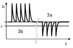
The fast pulses of ISO 7637-3 are based upon waveforms 3a and 3b of ISO 7637-2. These pulses occur as the result of switching processes. The characterization of these pulses are influenced by disturbed capacitance and inductance of the wiring harness.
The associated images illustrates the waveform associated with each pulse. These pulses are somewhat comparable to electrical fast transient (EFT) pulses according to IEC 61000-4-4 and can be injected in a similar manner with a coupling clamp.
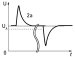
The slow pulses of ISO 7637-3, which are both the positive and negative pulses of ISO 7637-2, can be seen on the image on the left. These pulses can be tested using the ICC or DCC methods, however cannot be performed using a capacitive coupling clamp in accordance with the CCC method.
Both series of waveforms include requirements for both negative and positive waveforms with the slow pulses referring to 2a negative. This can be accomplished for pulse 2a by switching the direction of the probe which is discussed further in the ICC section.
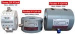
Transient Generators
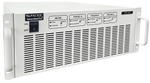
Automotive micropulse/microburst generators designed around ISO 7637-2 criteria typically generate pulses 1, 2a, 3a, and 3b and will provide capabilities for external equipment designed for ISO 7637-3 testing. These generators typically include a built-in coupling decoupling network (CDN) as well as HV direct out 50 Ohm connection.
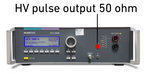
The image on the right shows the direct out connection on the EM Test UCS 200Neft/microburst generator. This direct output from the generator is used for connection regardless of the method. These connections can vary by type and the appropriate connectors must be used for the associated devices
Capacitive Coupling Clamp (CCC) Method
The CCL method is the most common and involves a using a capacitive clamp to inject fast pulses (ISO 7637-2 3a &3b) onto data or communication lines. These clamps offer the ability to inject pulses on cables up to 40 mm. A typical value will be around 100 pF, with a characteristic 50 Ohm impedance.
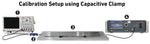
A major consideration in choosing this method is that it requires enough cable length to run the associated cable through the clamp which has a section for the cables measuring 1 meter in length. The associated image, provided from the EM Test ACC data sheet shows a brief overview of the setup and necessary cable length.
The exact design specifications are designed around ISO 7637-3 criteria found in section 5.4 for CCC features. These capacitive coupling clamps accomplish a similar result to those designed for commercial EFT/Burst testing to IEC 61000-4-4.
Verification & Adjustments
Verification and any necessary adjustments are done prior to conducting testing. During this first step no lines are present in the clamp and an 50 Ohm attenuator is needed that matches the BNC output connection of the clamp. These attenuators are included with the most capacitive clamps as well as a 1 meter coaxial cable.
- Oscilloscope
- KW 50 - 50 Ohm Attenuator
- EM Test ACC Clamp
- EM Test UCS 200N15
The setup for for the adjustment portion using the EM Test ACC, KW 50 attenuator and HVE 1 m connecting cable as well as oscilloscope can be seen on the associated image. It is important to note that given the two 50 Ohm loads, the voltage measured will be twice as large as the test voltage.
Testing
The associated severity levels of the associated pulses need to align with those provided in ISO 7637-1 and pulse adjustments should be made from the generator if necessary. Following the necessary adjustments testing can be conducted following setup requirements in section 4.5.4 DUT test, specifically Figure 2.
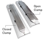
The associated image shows an EM Test ACC clamp both open and closed. The supply lines associated with the DUT are not placed in the clamp, however ground or supply lines delivered by the EUT will be.
Inductive Coupling Clamp (ICC) Method
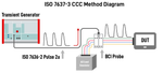
Inductive coupling is an injection method that uses a bulk current injection (BCI) probe/clamp to inject both the slow pulses (ISO 7637-2 2a) onto a series of cables or a bundle. This method lends itself well to large groups of data lines where the clamp feature allows for it to be easily placed around the bundle. Negative polarity of pulse 2a can be achieved by reversing the position of the injection probe around the corresponding wires.
The image on the right shows the most common injection probes which typically provide capabilities up to 400MHz, with some designed for IEC 61000-4-6 compliance at 230Mhz. When evaluating different probes, it is important to consider the window size, as not all offer the same openings which will limit the bundle size.
These probes are used with calibration fixtures designed to allow for verification of different testing criteria. These devices are typically not interchangeable with different manufacturer's or models and should be purchased with the corresponding probe.
Verification & Adjustment
Waveshape verification (and subsequent adjustments) are required to be verified prior to testing which includes both pulse risetime and duration values. During this process the generator settings may need to be adjusted to meet current requirements presented in the associated test levels. This setup has the potential for significant loss so it is crucial that this step is performed.
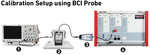
- Oscilloscope
- BCI Probe & Fixture
- INA 5580 Matching Network
- Teseq NSG 5500
Testing
Conducting tests for the the slow pulses using the coupling clamp is done in a very similar methodology as the calibration, with considerations given for the setup indicated in Figure 7 of ISO 7637-3. A straight harness method aligned with ISO 11452-4 can also be used.
Direct Capacitive Clamp (DCC) Method
The DCC method of injecting transient uses a series of resistors to inject pulses directly onto data or communication lines. This method can be done for both the fast pulses as well as the slow pulses with the correct corresponding capacitors. A major shortcoming of this method is that unless testing twisted and balanced symmetrical cables, lines must be tested individually.
ISO 7637-3 pertains to transient testing coupled onto data or communication lines with a limited number of pulses, ISO 7637-2 is tested to on power lines.
The generator will need to be able to provide pulses 2a, 3a, and 3b. This is most often done with a microburst generator in accordance with ISO 7637-2. The coupling device will be determined by the underlying method, a capacitive clamp or BCI probe are the most common.
References:
14:00-17:00. (n.d.). ISO 7637-2:2011. ISO. https://www.iso.org/standard/50925.html
AMETEK CTS | ACC. (2019). Ametek-Cts.com. https://www.ametek-cts.com/products/brands/em-test/acc
for, O. (2016). ISO 7637-3:2016. ISO. https://www.iso.org/standard/59603.html
