Conducted Susceptibility - Common EMI Tests, Requirements, & Setups
Conducted Susceptibility
Conducted susceptibility is the impact (or lack of impact) that transients or unintended signals have on equipment that is transmitted via direct physical contact. This criteria of testing is similar to that of conducted immunity, a term that is more commonly used in commercial and automotive applications(1). We will be focusing on MIL-STD-461G series of tests, specifically those tests that are commonly done during electromagnetic interference testing.
What is Conducted Susceptibility Testing?
Conducted susceptibility testing is a series of requirements, commonly MIL-STD-461, that equipment under test are exposed to where interference and transients are transmitted via physical connection either through power or data lines.
MIL-STD-461G: Electromagnetic Interference Characteristics of Equipment is the military test standard that establishes requirements for the electromagnetic compatibility (EMC) of devices and systems. Created by the DoD, (it can be downloaded free of charge from the DoD by clicking here) MIL-STD-461G uses "CS" designation for all conducted susceptibility tests, as well as "CE", "RE", and "RS" for related EMC tests. Our focus on susceptibility tests will involve a few main events and the related subsections which describe the testing requirements.
Susceptibility Tests
There are 10 requirements within MIL-STD-461G which are conducted susceptibility tests, prior versions of the standard may have different testing criteria as well as test themselves may have been added or removed. This can be seen with CS117 being added and CS106 removed in the newest MIL-STD-461G released in 2015. A more detailed description of the revisions and associated dates can be found by clicking here.
We will focus on a few underlying EMI events that pertain to multiple sections. While MIL-STD-461G requirements are different from commercial and automotive applications many similarities exist in testing and equipment. Below are a few of the categories of testing and associated sections.
- Conducted RF - CS114
- Transients - CS115, CS116, & CS117
- Ripple Test - CS101
- Electrostatic Discharge - CS118
Transient Tests
Transient tests are one of the most commonly conducted susceptibility tests and are covered in sections CS115, CS116, and CS117. As opposed to other transient immunity tests in commercial and automotive applications, tests are conducted using an injection probe/clamp instead of a coupling decoupling network (CDN). This allows for bundles of cables or wires to be tested as a whole, as opposed to the use of CDN which requires specific coupling equipment for each cable/connector type.
The associated video focuses on the Solar Electronics solution for CS115 and CS116 testing.
This video includes:
- Overview of Solar Transient Equipment
- List of Common Accessories
- CS115 & CS116 Injection Devices
Additional information on specific accessories or equipment for these tests can be found on the Solar Electronics MIL-STD-461 equipment guide.
Consistent with other requirements of MIL-STD-461G verification of key criteria is required prior to conducting testing. During the calibration process, the required test levels are saved, and waveform/test requirements are stored. For these transient tests, this is commonly done with voltage and current monitoring probes and the use of a capable oscilloscope.
MIL-STD-461 CS115 - Fast Transients
The CS115 test is designed to replicate fast transients (commonly switching transients(1))coupling onto lines exposing the EUT to short-duration pulses. Like other CS tests in MIL-STD-461 the transients are injected with a probe. As with other switching and power line transients such as those in IEC 61000-4-4 and ISO 7637-2, the pulses are often tested in bursts of rapid succession or a series of pulses.
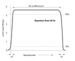
A simplified waveform based upon CS115 requirements is shown on the right. The test concept is consistent with our test methods where calibrated levels are applied the the EUT. While during verification the waveform should look close to the one provided above, during testing the waveform will likely be distorted (1).
CS115 Setup & Equipment
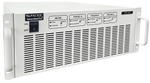
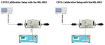
Some of the equipment used in MIL-STD-461 CS115 can also be used for CS116. This is particularly true of the injection devices, with both the two most common manufacturers Solar Electronics and EMC Partner allowing capabilities for both. The EMC Partner MIL-MG3 test platform can be used for both and is designed with separate modules for each. The below images illustrate the calibration setup for both CS115 and CS116 tests with the EMC Partner MIL-MG3.
MIL-STD-461 CS116 - Damped Sinusoidal Transients
CS116 is one of the most commonly conducted susceptibility tests for transients. The test involves injecting a damped sinusoidal waveform at varying frequencies onto cables using an injection probe. This test is covered in section 5.14 with figures CS116-3 and CS116-4 pertaining to the setup and calibration of the equipment.
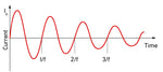
The damped sinusoidal waveforms are based on the peak current level where the current decays over time following the damping factor. The associated image illustrates a typically damped sinusoidal waveform in accordance with Figure CS116-1.
This test covers from 10 kHz to 100 MHz, with six frequency ranges required to be tested (10 kHz, 100 kHz, 1 MHz, 30 MHz, and 100 MHz) as well as additional critical frequencies.
CS116 Setup & Equipment
The equipment needed for this test must generate the required damped sinusoidal transient which is verified prior to conducting testing. A complete list of the required equipment from the standard can be found in section 5.14.3.2 Test equipment.
During the calibration process the amplitude of the waveform is adjusted to meet the required level and the damping factor is calculated and recorded. The setup illustrates the test setup and concept for the calibration of CS116 using Solar Electronics equipment.
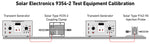
As we mentioned earlier this standard has potential requirements for more than 6 recommended frequencies. This can be accomplished in different ways by different test system manufacturers, however the most common is a variable frequency module from Solar Electronics. These modules offer the flexibility of selecting any frequency within the range using a manual turn-style.
MIL-STD-461 CS117 - Indirect Lightning
Section CS117 is designed to test the impact of indirect lightning transients on an EUT. The testing in this section, given the underlying event, is the most complex and costly to perform. This test is particularly conducted on flight or safety critical equipment and is similar to tests in civilian aviation in RTCA/DO-160.
The two different categories of tests, multiple stroke and multiple burst cover 6 different waveforms. These waveforms include 5 impulse transients and one damped sine or cosine wave-shape (voltage waveform 3). The different waveforms include both current and voltage pulses. The multiple burst tests includes waveform 3 at 1 MHz and 10 MHz as well as waveform 6. The test levels for these waveforms are split between internal and external equipment levels.
CS117 Testing
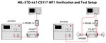
As with other tests, a calibration is conducted prior to beginning the testing process. This will involve the use of an injection probe and monitoring devices allowing for waveforms to be verified. The below setup illustrates how the calibration and test setup would look using the EMC Partner AVI3000/AVI-LV3 and CN-BT7 injection probe. For MIL-STD-461 CS117 testing it is necessary to use the CN-GI-CI-V coupler for WF4 and WF5A.
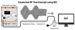
Bulk Cable Injection Testing - CS114
This section of MIL-STD-461G is in many ways similar to that of other Conducted RF immunity tests with the use of an injection probe and the substitution method. This test requires a signal generator, amplifier, power meter, etc. as indicated in 5.12.3.2. For general information about Conducted RF immunity tests check out our post which focuses specifically on these tests.
Unlike other conducted RF requirements, CS114 has a frequency range from 4 kHz to 200 MHz and makes a distinction between different branches with Navy starting the lowest at 4 kHz. This standard also has high test levels with curve #5 going as high as 109 dBuA.
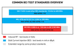
The associated image provided from the data sheet from the Teseq NSG 4070 test system provides the associated frequency ranges of common conducted RF requirements. It is important to take note that, unlike other common requirements, equipment designed for the Navy could potentially begin testing at 4 kHz instead of the more common 10 kHz.
The concept for this test is to inject a 1 kHz pulse modulated signal at 50% duty cycle using an injection probe based upon forward power levels set during calibration while monitoring the induced current. Prior to testing, see Figures CS114-3 and CS114-4, both the monitoring probe and injection probe are calibrated and levels stored. The cable impedance that is being tested can have an impact when applying forward power, it's recommended for shielded cables or low impedance circuits to increase the signal gradually.
CS114 Calibration & Testing
The procedures required by CS114 are calibration (5.12.3.4 b), verification (5.12.3.4 c), and finally EUT testing (5.12.3.4 d). Typically testing for these types of test are done using software allowing for data and necessary levels to be quickly checked and stored expediting the testing procedure.
The associated video illustrates how the Amplifier Research CI000402 test system can be used for CS114 along with the Teseq CIP 9136A injection probe. The video includes:
- Overview of Equipment
- Test Setup using System
- EMCware Software
- Running System Calibration
MIL-STD-461 CS101 - Ripple Test
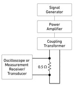
The purpose of this test is to evaluate the impact that coupled signals have on input power leads. This is accomplished by using a signal generator and power amplifier and then injecting them onto the power leads using a coupling transformer. A complete list of equipment can be found in section 5.7.3.2 with Figure CS101-3 for calibration and Figures CS101-4 to Figures CS101-6 for testing.
This test is started by first determining the necessary signal level to reach a voltage corresponding to the required power level based on Figure CS101-2 across a 0.5 Ohm resistor. This process is done across the frequency range of interest saving the associated levels to be applied later during testing.
Recently there have been ongoing discussions on this requirement, specifically the method used to limit the power. The MIL-STD-461 CS101 Test Method Review at Interference Technology walks though this in more detail. There are two methods of making measurements of the applied signal:
- Using an oscilloscope with a power input isolation transformer
- Using a measurement receiver together with a transducer
What is the purpose of the CS101 Conducted Susceptibility test?
The purpose of CS101 is to test the impact that ripple voltages associated with power waveform distortion has on the operation of the equipment under test (EUT).
Test Equipment
The equipment requirements for this test are explicitly stated in section 5.7.3.2 which includes considerations for both methods. While the most common accessories may be readily available, the power amplifier and coupling transformer are the most difficult to find.
AE Techron provides a solution for both the power amplifier (typically model 7224) and a variety of different coupling transformers. They offer a variety of different transformers, however the T2000 is commonly used for CS101. Additional accessories including the 10 uF capacitors and 0.5 Ohm Resistor designed specifically for this application can be purchase through Solar Electronics. The guide on the Solar Electronics website a list of the most commonly required accessories for each test in MIL-STD-461G.
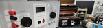
The related video is an overview of the AE Techron 7224 and includes adjusting the gain to amplify the required signal. During the video the 3110A waveform generator is used to create the input sine wave. A very similar setup with a few additional accessories can be used during the calibration as shown above. This video includes:
- Overview of Test Systems
- DIP Switch Configuration
- AC & DC Waveform Adjustments
MIL-STD-461 CS118 - ESD
Electrostatic discharge testing requirements were a recent addition to MIL-STD-461G in 2015. As with other common requirements, such as CE Marking and IEC 61000-4-2a, a 150 pF/330 Ohm network is used with testing up to +/-15 kV air discharge and +/- 8 kV contact discharge. Air discharge is only used when contact discharge cannot be applied.(2)
A unique feature of CS118 test is the use of a Ionizer or 1 megaohm resistors as a methodology for removing built-up charge on an ungrounded EUT/DUT. This test also requires a circuit inductance of 5 Microhenry or less on the ESD test system. This inductance requirement is included in many common test requirements including IEC 61000-4-2 and should be verified with the manufacturer to ensure compliance.
ESD Test Levels and Waveforms
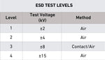
ESD pulses include both current and voltage components, with current waveform criteria (rise time, duration, etc.) verified for compliance to a particular standard.
ESD test levels for CS118 include 4 levels at both positive and negative polarities. The associated table is based on Table 8 of CS118.
The waveform of MIL-STD-461 CS118 is the same as IEC 61000-4-2 and should be verified as well as the test level. The image below illustrates an ideal current waveform based on figure CS118-4.
Susceptibility Test FAQ
In most cases conducted susceptibility and immunity can be thought of interchangeably, with susceptibility being mostly used in military applications.
Conducted susceptibility is the impact that unintended signals have on equipment which are transmitted via power or data lines.
References:
(1) Ferguson, S. (2019, March 27). Review of MIL-STD-461 CS115 Impulse Excitation; CS109 Structure Current; RS105 Transient Electromagnetic Field | Interference Technology. Interference Technology. https://interferencetechnology.com/review-of-mil-std-461-cs115-impulse-excitation-cs109-structure-current-rs105-transient-electromagnetic-field/
(2) MIL 461 CS118 Conducted Susceptibility Testing | Keystone Compliance. (2024, November 18). Keystone Compliance. https://keystonecompliance.com/mil-std-461/cs118/
