ESD Testing - Overview, Methods, Testing Explained

Electrostatic Discharge
While the zap of an Electrostatic (ESD) event is only a slight annoyance to people, it has the potential to cause damage or malfunction of electronics. The quick release between two objects can reach thousands of volts while remaining a fairly low-energy event. The buildup of electrostatic charge is most commonly created by the contact and separation of two materials.
What is ESD?
Electrostatic discharge (ESD) is the rapid release of energy between two objects with different potential charges, commonly through an air discharge, caused by the buildup of static electricity.
The buildup of charge can occur from humans as well as objects, which is commonly seen in industrial processes and manufacturing. The impact ESD has is a major consideration in many applications including commercial, avionics, military, and automotive. The associated video from the Hoffmann Group provides an excellent overview of the basics of electrostatic charge.
ESD Testing
ESD testing is commonly done as part of electromagnetic compatibility (EMC) testing where the impact of a discharge is evaluated on the operation of the equipment under test (EUT). While the underlying event remains the same, how the testing is done will vary based on the requirement and application.
ESD testing is also conducted at both a system level and component level. These two different types of testing will have significant differences and will require specialized equipment for each. Our main focus will be on system-level ESD testing and requirements.
What is ESD Testing
Electrostatic Discharge testing is an EMC immunity test designed to ensure that products can operate without deterioration when exposed to the quick release of energy of an electrostatic event.
Handbooks & Application Notes
The list below of application notes, guides, and handbooks provides an excellent background on ESD as well as some of the most common requirements.
Nexperia - ESD Application Handbook
EMC Standards - Handbook on EN 61000-4-2
Ametek CTS - ESD Workshop
Teseq - ESD Equipment Guide
Test Levels & Waveform
Electrostatic discharge pulses have both voltage and current components which are set by the relevant testing standard. This will typically include rise time, duration, voltage levels as well as other requirements.
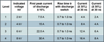
The information in the table provided by the Teseq NSG 435 user manual provides the relevant information for IEC/EN 61000-4-2, Ed. 1.2:2001 for contact discharge. This requirement is the most common for commercial applications and from the table in level 4 reaches up to 8 kV.
ESD Current Waveform
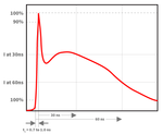
The current waveform criteria is a major component of most ESD testing requirements where waveform criteria such as rise time and duration are verified. The equipment used to conduct ESD testing is typically designed according to these specifications and is often verified annually as part of an ISO 17025 calibration.
The associated waveform based on IEC 61000-4-2 requirements illustrates a typical current waveform.
What is the Time Between ESD Discharges?
The time between ESD discharges is typically one second for commercial applications, with slightly longer intervals if needed to determine the impact on the EUT.
ESD Testing Polarity
ESD testing also includes a polarity component where both positive and negative pulses are applied if required by the underlying test standard. In many applications, including automotive, testing is required with both positive and negative polarities.
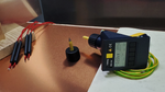
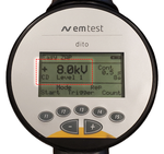
This is also a requirement placed on the design of the simulator where it must be able to provide both polarities. The associated image shows the positive polarity selected on the EM Test Dito.
Discharge Methods
The two most common discharge methods when conducting ESD are air and contact discharge. Both methods are referenced by a variety of standards with contact often being preferred if it can be used. Most test requirements will have different levels based on the discharge method that is used, with air discharge having higher levels than contact discharge.
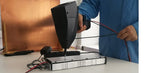
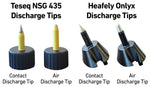
The design of both the air and contact discharge tips for system-level testing are often based on the same criteria regardless of the application or standard. The associated image illustrates how air and contact discharge tips look for both the Teseq and Haefely ESD simulators.
What is ESD air discharge method?
The air discharge test method is when the ESD simulator is moved towards the EUT until the distance is small enough causing a discharge through the air gap to the EUT.
Air Discharge

The air discharge method of testing is commonly used for replicating real-world ESD events and can be required by testing standards. This method can cause the impulse current waveforms to which the equipment is subjected to vary significantly from pulse to pulse. This method is commonly used in commercial ESD test requirements when the contact discharge method cannot be used.
The air discharge tip is used for this test which is rounded to facilitate the arching across the air gap. These tips are commonly designed in accordance with IEC 61000-4-2 which places requirements on the design. There are many factors that have the potential to impact testing when the air discharge method is used:
Humidity - The lower the humidity the higher probability of a electrostatic discharge event occurring.
Temperature - The lower the temperature often leads to an increase in ESD events.
Speed of Approach - Attempt to duplicate the recommended speed ensuring compliance.
Contact Discharge
The contact discharge method is the preferred method for a variety of ESD testing requirements including that of IEC 61000-4-2. This method requires surface conductivity at the point where the discharge will be applied. It has the benefit of ensuring the consistency of the waveforms and is faster given discharges can be applied at a relatively fast pulse repetition rate.
What is ESD contact discharge method?
The contact discharge method is when the simulator makes direct physical contact with the EUT while applying ESD pulses.
ESD Testing Standards
Electrostatic discharge testing is typically done to a particular standard or requirement. The standard is either followed completely for full compliance to the requirements or partially for pre-compliance. When we look at ESD testing often we're referencing basic standards, which are called out in both product and generic standards.
IEC 61000-4-2
IEC 61000-4-2 is a commercial testing requirement designed for testing immunity to ESD events. This requirement is commonly referenced by product-specific requirements where part or the complete test will be referenced. This standard is currently in edition 2 and defines typical waveform of the discharge current, range of test levels, test equipment, test setup, test procedure, calibration procedure and measurement uncertainty.
This standard requires a 150 pF/ 300 Ohm network and typically limits to testing to 16 kV air and 8 kV contact discharge. It also applies discharge to a vertical coupling plane as well as air and contact discharge.
Automotive
Automotive ESD testing is different from testing commercial or military applications because of the amount of international and OEM requirements. Of the automotive ESD standards, ISO 10605 is the most common, with others often having similar requirements. ESD testing for automotive equipment often also involves testing ungrounded equipment where the charge has to be removed prior to applying the next discharge.
ISO 10605 applies to all types of road vehicles, simulates ESD from a human body inside or outside a vehicle, and has unique equipment requirements. ISO 10605 testing typically includes three additional networks 150 pF/ 2k Ohm, 330 pF/ 2k Ohm, and 330 pF/ 330 Ohm. Testing is also conducted from 2 kV up to 25 kV in both polarities.
Military
The two most common military requirements are MIL-STD-461 CS118 and MIL-STD-883. MIL-STD-461 is the most common series of tests for equipment used in military applications with section CS118 focusing on personnel borne ESD.
MIL-STD-461 can be downloaded directly from the DoD by clicking here. It has very similar test levels and requirements as IEC 61000-4-2 and includes verification/calibration procedures in section 5.16.3.3 section c. This typically includes the use of an electrostatic voltmeter used to verify the output voltage of the ESD simulator. The test levels reach up to 15 kV and a 150 pF/ 330 Ohm ESD network is used for testing.
Component Level ESD Requirements
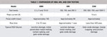
Component-level ESD testing can be broken down into three main categories, human body model (HBM), machine model (MM), and charge device model (CDM). The below table which is from the EDN article relating to ESD provides an excellent breakout of the different features of each.
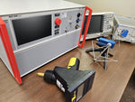
ESD Test Equipment
Electrostatic discharge (ESD) simulators or guns are the devices that generate the rapid release of voltage and current designed to meet testing requirements. These devices are commonly designed around IEC 61000-4-2 with additional functionality added to meet more specialized applications.
The simulators are often designed so they can meet a variety of testing requirements by switching the discharge network or discharge module. The voltage levels for both air and contact discharge can vary by manufacturer with some units offering capabilities for both up to 30 kV.
Discharge Tips
Simulators that are available on the market today should include both air and contact discharge tips. How the tips connect and are removed from the main unit or pistol varies by manufacturer and model. These tips are designed in accordance with IEC 61000-4-2 but are used in testing for a variety of requirements and applications.
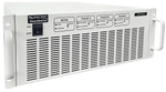
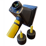
The image shows the Teseq NSG 435 simulator contact and air discharge tips which turn on the front of the system. There are also additional tips available allowing for adjustment of the rise time and different testing methods. These are commonly used for special applications and often not needed for commercial requirements.
Resistance Capacitance (RC) Module/Network
The RC network or module is a component of the ESD simulator which determines the resistance and capacitance values which are required by different test standards. Depending on the model and manufacturer these can switched out or built-in the equipment. These different combinations are used to replicate different real-world situations, with some applications requiring multiple networks or modules for testing.
ESD Voltage & Waveform Verification
The verification of both the voltage and current criteria of ESD simulators is typically done on an annual basis, however some testing standards require verification before or after each series of tests. It is also commonly done on a periodic basis to ensure the equipment is functioning correctly.
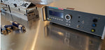
Verification of voltage levels of a simulator can be done through a few different method, however is often done through either a voltmeter or voltage divider. Common voltage verification devices include:
EMC Partner ESD-VERI-V Divider
The video on the left shows how the ESDEMC ES105 is used to verify voltage levels with the Haefely ONYX16 ESD simulator.
The current waveform is also commonly verified before and after testing especially when conducting military or avionic tests. This requires special equipment as well a ground plane and ESD target.
ESD Test Setup
The test setups for ESD testing will vary by the underlying standard or application, with commercial applications commonly to IEC 61000-4-2. To accommodate larger equipment not able to be placed on a table there is also a setup designed for floor-standing equipment.
The ESD test setups can either be made internally, manufactured locally, or purchased. The video below walks through the tabletop setup of IEC 61000-4-2. It includes an overview of the all major components including coupling planes, table, and accessories.
What is the ESD Test Setup?
The table top test setup for ESD includes ground coupling plane, horizonal and vertical coupling planes, all wood table, as well as bleed off cables and insulating support.
Table Top Setup
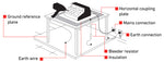
The most commonly used setup is the table top setup where the equipment under test is placed on top of the table and testing is conducted. The diagram below from the Teseq NSG 437 user manual provides an overview of the major components.
Floor Standing Setup
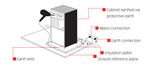
Equipment under test that is too large to be placed on a table is tested using the floor-standing EUT test setup.
Current Waveform Verification
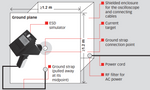
When capturing current waveforms the surrounding environment's noise has the potential to impact results. Typical required equipment for this setup includes:
- ESD Target & Adapter
- 20 dB attenuator
- Oscilloscope with >1 GHz
- Plane for Target to be Mounted
Conducting Testing (Applying Discharges)
Once the testing requirements/standard, level, setup, and other criteria are established they are written in the test plan. The test plan is the formal document that provides all the details about the product, tests, and results. For pre-compliance testing, certain requirements in the standard may be removed or changed, with ESD this typically relates to setup requirements.
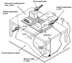
Discharges will typically be applied with three different methods
- Indirect Application to HCP
- Direct Application
- Indirect Application to VCP
It is also possible for additional testing methods using specialized equipment including H-field and E-field adapters.
The equipment under test will be running in normal modes of operation during ESD testing, or in its most sensitive mode. For troubleshooting or replicating a failure specific modes of operation may be the focus to allow redesigns/modifications of the EUT to be evaluated.
Test Point Selection
Test point selection criteria can vary slightly based on the underlying standard, however, all focus on applying discharges to common points of contact during normal operation. For commercial testing to IEC 61000-4-2 exclusions are listed in 8.3.2 and table 4 includes cases for the application of ESD on connectors. MIL-STD-461F has a requirement for test points "As a minimum, each face shall be included."
Test Level
While test levels are provided in the standard for compliance testing, a more gradual increase in voltage is recommended for troubleshooting and pre-compliance testing. By slowly increasing the voltage at set increments and monitoring the operation of the equipment under test it can more easily be determined at what level any deterioration of the function occurs.
ESD Test FAQ
ESD stands for electrostatic discharge.
ESD testing is the process of applying a series of fast, high-voltage pulses to replicate an electrostatic discharge event.
An electrostatic discharge is typically measured by voltage and current measurements.
References:
Desco. (2012, July 30). ElectroStatic Discharge (ESD) a Person Can Feel | DESCO. DESCO. https://desco.blog/2012/07/30/electrostatic-discharge-esd-person-can-feel/
Ferguson, S. (2018, October 12). Review of MIL-STD-461 CS118 – Electrostatic Discharge | Interference Technology. Interference Technology. https://interferencetechnology.com/review-of-mil-std-461-cs118-electrostatic-discharge/
EDN. (2011, October 6). Understanding and comparing the differences in ESD testing - EDN. EDN. https://www.edn.com/understanding-and-comparing-the-differences-in-esd-testing/
IEC 61000-4-2:2008. (n.d.). Webstore.iec.ch. https://webstore.iec.ch/en/publication/4189
ISO 10605 Road Vehicles Test Methods for Electrical Disturbances from Electrostatic Discharge. (n.d.). Retrieved January 20, 2025,
from https://www.ti.com/lit/an/slva954b/slva954b.pdf?ts=1737395212036
StackPath. (n.d.). Www.ecmweb.com.
https://www.ecmweb.com/content/article/20897138/electrostatic-discharge-causes-effects-and-solutions