Conducted Immunity Testing - Equipment, Tests, & Setups

Conducted Immunity Testing
This type of testing is conducted as part of electromagnetic compatibility (EMC) testing which includes emissions and radiated immunity testing. Testing is done for product reliability and certification which can be required before the product can be brought to market.
What is conducted Immunity Testing
Conducted immunity testing is the process of evaluating the impact that interference has on the operation of electronics transmitted by physical connection.
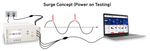
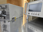
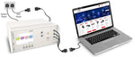
The image on the right illustrates how a transient generator is used to generate electrical surges on the AC power mains. This type of testing can include a variety of different tests as determined by the manufacturing team and test lab, but will commonly include:
- Transient Testing
- Electrostatic Discharge (ESD)
- Conducted RF Testing
- Voltage Dips, Variations, & Interruptions
Conducted Immunity Test Standards
There are many product specific standards that exist which include system-level immunity testing requirements, however they often reference the international generic requirements. The most commonly used and referenced standards in North America and Europe are those from the IEC (International Electrotechnical Commission). The IEC 61000-4 series is often used which pertain to Electromagnetic Compatibility (EMC) testing for residential, commercial, and industrial applications. A list below are some of the most common used for conducted immunity testing:
- IEC 61000-4-2 - Electrostatic Discharge
- IEC 61000-4-4 - Electrical Fast Transients
- IEC 61000-4-5 - Combination Wave Surge
- IEC 61000-4-6 - Conducted RF Disturbances
- IEC 61000-4-11 - Voltage Dips & Interruptions
- IEC 61000-4-12 - Ring Wave Test
The exact standard(s), requirements, and methods used are determined by the EMC test plan. This guiding document provides an easy to read report providing relevant EMC tests that were conducted, under what conditions, and the results.
Transient Testing
Electrical transients are caused by a wide range of culprits and have the potential to cause impacts to the operation of electrical systems. These rapid changes in energy can be transmitted device-to-device or at the component level.
There are a variety of different causes of transients, some being internal and some external. It is estimated that between 60-80%(1) of surges, a common transient, are created within a facility as opposed to externally.
Transients are defined by their waveform and aim to replicate the underlying event causing the interference. These pulses can be compromised of voltage and current components and can vary by risetime, duration, oscillation as well as associated level. They are separated into impulse transients and oscillatory transients, with impulse being commonly used in immunity testing.
Electrical Fast Transients (EFT) - IEC 61000-4-4
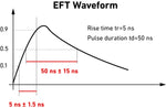
Electrical fast transient testing, also referred to as burst testing, is one of the most common immunity tests. These fast rise time, short-duration events, occur in quick succession and are commonly tested on both power and data lines. The most commonly test standard for both certification and product reliability is IEC 61000-4-4 which is commonly referenced by more generic standards.
These pulses have a rise time and duration of 5us/50us and are not commonly synchronized when testing AC power.
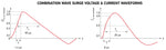
Combination Wave Surges - IEC 61000-4-5
Electrical surges in accordance with IEC 61000-4-5 have both a current and voltage waveforms, leading them to be referred to as combination wave surges. While both voltage and current surges are also tested individually, it is far less common. For the our discussion we will focus on the most common waveform within the standard, 1.2/50us voltage open-circuit and 8/20us short-circuit.
When discussing surges it is common to hear them described in a rise time and duration format voltage format and associated test level. This is useful when describing IEC 61000-4-5 testing as this standard also includes a 10us/700us telecom surge waveform.
Conducting Testing
Testing for transients applies the waveforms to the cabling going towards the associated port which testing is being conducted on. This methodology is applied for both power on and power off tests as well as those for power, data, and communication ports. While devices like capacitive coupling clamps are used for EFT testing data lines, coupling decoupling networks or CDNs are commonly used for surge tests.
A variety of different testing criteria can be changed or adjusted using the software including test level, coupling path etc. It is important to note that all power-on testing must be done through the CDN otherwise damage to the test system will occur! This may require the use of an external power source going into the CDN depending on the EUT/DUT.
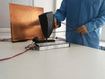
The injection of EFT pulses onto data lines is commonly accomplished through the use of a capacitive coupling clamp. This can done by connecting the clamp to the EFT output on the transient generator and placing the cables in the clamp. Generally speaking, capacitive clamps are interchange with transient generators so long as the cable has the correct connectors. This offers an easy solution for the majority of data line testing, this cannot be done with combination wave surges which require CDNs.
Electrostatic Discharge - IEC 61000-4-2
Electrostatic Discharge, commonly called ESD, is one of the most immunity tests. Electrostatic discharge can be thought of as the rapid release of energy between two differently charged objects caused by the buildup of static electricity. This type of testing is done at both component level and system level, with different requirements for each.
ESD testing is defined by the voltage test level and current waveform as well as the resistance capacitance requirements. This is commonly 150pF/300Ohms as required by IEC 61000-4-2 one of the most commercial system level standards.
A series of pulses are applied to the EUT or DUT at regular intervals using either the air discharge or contact discharge method. For commercial testing contact discharged is the preferred method, with air discharge often used when contact cannot be applied.
ESD Test Levels and Waveforms
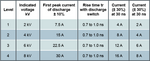
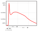
Electrostatic discharge pulses have both voltage and current components which are set by the relevant testing standard. This will typically include rise time, duration, voltage levels as well as other requirements.
The information in the table provided by the Teseq NSG 435 user manual provides the relevant information for IEC/EN 61000-4-2, Ed. 1.2:2001 for contact discharge. This requirement is the most common for commercial applications and from the table in level 4 reaches up to 8 kV.
The current waveform criteria is a major component of most ESD testing requirements where waveform criteria such as rise time and duration are verified. The equipment used to conduct ESD testing is typically designed according to these specifications and is often verified annually as part of an ISO 17025 calibration.
The associated waveform based on IEC 61000-4-2 requirements illustrates a typical current waveform.
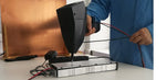
Air Discharge

The air discharge method of testing is commonly used for replicating real-world ESD events and can be required by testing standards. This method can cause the impulse current waveforms to which the equipment is subjected to vary significantly from pulse to pulse. This method is commonly used in commercial ESD test requirements when the contact discharge method cannot be used.
The air discharge tip is used for this test which is rounded to facilitate the arching across the air gap. These tips are commonly designed in accordance with IEC 61000-4-2 which places requirements on the design.
Contact Discharge
The contact discharge method is the preferred method for a variety of ESD testing requirements including that of IEC 61000-4-2. This method requires surface conductivity at the point where the discharge will be applied. It has the benefit of ensuring the consistency of the waveforms and is faster given discharges can be applied at a relatively fast pulse repetition rate.
Conducted RF Immunity - IEC 61000-4-6
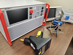
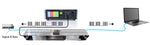
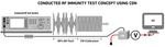
Conducted RF immunity testing replicates the exposure of equipment to electric or magnetic fields where interference travels down power or data lines towards equipment. When testing immunity to conducted RF noise or interference there are several injection methods as well as test methods that can be used. The most common, as well as the image shown below is using the substitution method with a coupling decoupling network (CDN) injection device.
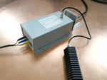
Injection Devices
There are three main injection devices used in conducted RF testing, coupling decoupling networks, electromagnetic (EM) clamps, bulk current injection (BCI) probe. Each of the three offers unique benefits, however testing requirements will typically provide guidance on which is appropriate.
IEC 61000-4-6, the most common commercial standards, explicitly states a preference for CDNs over other injection devices. CDNs are not only the most effective injection method, but given their design limit the variability of level injection the associated cabling.
It important to keep in mind with the associated device that the corresponding calibration fixture will be needed. In the case of IEC 61000-4-6 50 Ohm to 150 Ohm adapters will also be required during the calibration. How they're utilized during the calibration process can be seen in the associated video.
RF Immunity Testing
Conducted RF immunity testing using the substitution method as per IEC 61000-4-6 includes first calibrating the associated test system allowing for the system and software to set associated factors for a given test level. When this process has been completed, the calibration factors are removed and associated cables placed through the CDN for testing to begin.
Voltage Dips, Interruptions, & Variations
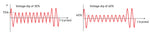
AC voltage dips, interruptions, and variations are tested as immunity events to IEC 61000-4-11 and IEC 61000-4-34. IEC 61000-4-11 applies to equipment up to 16 Amps per phase and IEC 61000-4-34 to 17 Amps or above, with single and three phase testing capable for each.
For voltage dips testing the standard places requirements on the number of cycles with the associated percentage reduction in voltage as well as rise/fall times. The images below demonstrate voltage dips on an AC sine wave.
Single Phase Testing
Conducting testing to IEC 61000-4-11 typically requires external equipment associated a transient generator or power supply to meet the rise and fall requirements. This is typically accomplished with a switch or motor variac which is designed to work with a particular model of test equipment.
The associated video walks though the EM Test Motor Variac NX 1-260-16. The video includes:
- Connections on the front & back
- Adding variac to the software
- Setting voltage dips levels
- Navigating voltage variations menu
- Voltage dip level verification
Three Phase Testing
Three phase testing to IEC 61000-4-11 and IEC 61000-4-34 typically requires a power supply and an external switch. Typically these switches require communication with the associated power supply and cannot be used with other manufacturers sources.
The associated video on IEC 61000-4-34 testing using the Pacific Power AFX series and EPTS-75A-3 provides a fully compliant solution for three phase voltage dips, interruptions, and variations. The video includes:
- Necessary connections
- Calibration procedures
- Conducting IEC 61000-4-34
Conducted Immunity Test Setups
The test setup used in conducted immunity testing will vary based on the underlying testing requirement as well as the size of the EUT. For floor-standing equipment, equipment too large, or equipment unable to be placed on a table, there is a modified setup that is used.
Some of the testing requirements such as those for ESD testing to IEC 610000-4-2 and EFT/Burst testing to IEC 61000-4-4 have explicit requirement whereas others are more vague. It's common in a laboratory setting to see the same setup used in multiple tests for table top equipment so long as enough consideration is given to the minimum requirements of the standards.
There are common components used in the majority of the setups used for immunity testing, these will include a ground reference plane, insulating support, and grounding cable connected to the plane. Some standards place preference on the type of metal used, however copper and aluminum are common.
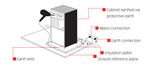
ESD Test Setups
The most commonly used ESD setup is the table top setup where the equipment under test is placed on top of the table and testing is conducted. The diagram below from the Teseq NSG 437 user manual provides an overview of the major components.
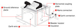
Equipment under test that is too large to be placed on a table is tested using the floor-standing EUT test setup.
Transient Test Setup
The generic setup for testing to IEC 61000-4-4 for table top equipment can be seen below from the user manual of the EM Test NX5. The guidelines from the associated test standard (as well as safety precautions) should be followed to ensure compliance and accurate results.
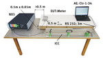
Typical test setups will include:
- Ground Reference Plane
- Transient Generator
- CDN (and Clamp if needed)
- Insulating Support
- Connection and Grounding Cables
Ground Reference Plane - Usually made of aluminum, copper, brass or other metal. Often times the same ground plane can be used for IEC 61000-4-2 if EUT sizing requirements are met. Copper and aluminum work excellent for this requirement, are malleable, and commonly referenced in a variety of conducted immunity setups.
Insulating Support - Most commonly polystyrene (Styrofoam), polypropylene or insulating foam-based products are used. When selecting for compliance to a particular standard, reference relative permittivity εr. A table of the permittivity/dialectic constant of common materials can be found at this Website.
Grounding Strap/Cable - These are especially important given safety with this type of testing. They are often included with the generator, however for specific sizing requirements they can be purchased here as well.
Immunity Testing FAQ
Conducted immunity testing is a subset of EMC testing where an equipment is subjected to a variety of interference transmitted via physical contact.
Conducted susceptibility testing is another term used interchangeably with conducted immunity, often in military and avionic applications.
The most common basic standards for conducted immunity testing are the IEC 61000-4 series of tests (these include IEC 61000-4-2, IEC 61000-4-4, IEC 61000-4-5 etc.) as well as others that pertain to the EUT/DUT.
References:
IEC 61000-4 - Electromagnetic Compatibility Package. (2016). Ansi.org. https://webstore.ansi.org/standards/iec/iec61000electromagnetic
IEC 61000-4-11:2020. (2020). Webstore.iec.ch. https://webstore.iec.ch/en/publication/63503
What Are Surges | NEMA Surge protection Institute. (n.d.). Www.nemasurge.org. https://www.nemasurge.org/history/