Surge Generators - Test System Overview & How to Use
Surge Generator Overview
Surge generators encompass a wide range of test systems all of which are designed to replicate different waveforms used to test the immunity of a device or equipment to a particular standard or requirement. These systems will generate either a voltage waveform, a current waveform, or in the case of combination waveforms both which the equipment under test (EUT) will be subjected.
What are Surge Generators?
Surge generators are testing devices used to produce fast rise time, short duration waveforms commonly used to replicate both indirect lightning and power grid switching transients on data or power lines.
Surge generators fall into the larger category of immunity test equipment which is commonly tested along with electrical fast transients (EFT) and electrostatic discharge (ESD) tests. Given that these transients can be lightning generated, they have the potential to be tested at high levels, particularly in outdoor lighting applications.
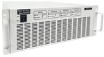
Sections of a surge generator
The designs of these test generators will vary by manufacturer, however the majority provide three main sections used during testing shown below.
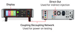
Coupling Decoupling Network (CDN): Connected to power ports on EUT/DUT for power on Testing
Direct Out Connections: Connected to ports for power-off direct injection testing
System Display: Used for selecting criteria and test routines
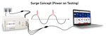
Surge Testing Concept
The surge immunity test is commonly conducted by two methods, direct injection and through the use of a coupling decoupling network (CDN). The direct injection method is a power-off test where the surge is directly applied to the EUT ports. The CDN method is used for power on testing, where the equipment operates under normal conditions while the waveforms are applied to the associated cabling.
Testing Requirements/Standards
Many product-level standards have surge testing requirements, however there are three different standards we'll consider, IEC 61000-4-5, ANSI C37.60.1, and the two most common telecommunications standards Telecordia GR-1089 and ITU-T K.
Test criteria for surges are commonly defined by the test level, and the waveform's rise time and duration requirements. The rise time and duration waveform specifications are determined by the underlying standard and can typically not be changed on the generator. The voltage/current can vary from as low as 100V to the maximum specified by the generator, usually 4000 or 6000 volts.
IEC 61000-4-5
This standard is the most common international surge test requirement and includes waveforms and testing specifications. It also places testing requirements on both power and data line ports and specific requirements on the generators used for testing. For more information on this standard, you can reference the standard itself from the link above or the handbook written by EMC Standards by clicking here.
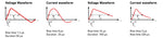
The two most common combination waveforms of this standard can be found below. As mentioned previously these pulses are defined by a few different features, most notably the rise time and duration of both the open-circuit voltage and closed-circuit current waveforms. The images below illustrate both the combination wave surge pulse and the telecom surge pulse associated waveforms.
Surge generators designed around this standard will also meet the phase angle requirements, where the waveforms are imposed on specific angles (0, 90, 180, 270) of the AC power sine wave. This is commonly already entered in the pre-programmed routine or can be manually adjusted either through the front panel or software.
ANSI C62.41
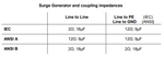
ANSI C62.41 and the associated sub-standards have very similar surge requirements to that of IEC 61000-4-5, in most cases the same generators are used for both. These standards both define the same voltage and current combination waveforms and have much of the same testing criteria. The most noticeable difference between the ANSI and IEC standards are the coupling requirement as shown in the image on the right.
Telecommunications (Telcordia & ITU-T)
he two most common telecommunications surge requirements areTelcordia GR-1089andITU-T K, with ITU-T K being used largely internationally and GR-1089 used mainly in the US. These standards include other waveform requirements specific to telecommunications systems, equipment, or centers as well as combination wave surges.
Selecting Testing Criteria
Selecting testing parameters can be done either through the display on the test system or through control software from the manufacturer. Most surge generators on the market today have the most basic test routines for IEC 61000-4-5 programmed into the system which can be accessed through the display. For more complex test routines or requirements the software offers more flexibility and programmability than working through the display.
Front Panel Display
The front panel display on surge test systems provides the fastest and simplest way to conduct testing. Many systems display include a quick start style of menu where the most common testing criteria can be modified and changed.
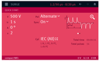
The quick start menu on the left from the EM Test NX5 provides the ability to quickly change a variety of criteria including:
- Voltage
- Time between pulses
- Number of pulses
- Polarity
- Phase Angle
Control Software
Testing or control software designed for use with these generators offers more flexibility and programmable routines than what is normally available through the front panel. While some systems include free basic software, typically it is necessary if you wish to utilize the manufacturer's software to purchase a keycode. Most software on the market today also offers test reports providing information on testing parameters as well as notes for the functionality of the EUT.
Using a Surge Generator for Testing Power Lines/Ports
There are two main methods for conducting surge testing discussed earlier, direct injection (power-off) and power-on testing using a coupling decoupling network (CDN). The most common of these is the power-on test which allows for the evaluation of the potential impact surges during normal operation of the EUT.
Most surge generators available on the market offer power CDNs that are built-in the generator itself providing an all-in-one solution. The built in CDNs designed for power lines typically have 300 Volt 16 Amp AC power limitations, EUT that require higher levels will require an external CDN.
The associated video using the EM Test NX5 generator is focused on the combination wave surge test and includes:
- Connections to Front & Back of Test System
- Modifying Surge Testing Criteria
- Selecting Preprogrammed Test Standards
- Using IEC.Control Software for Testing
Power Coupling Decoupling Networks (CDNs)
External Surge CDNs are designed to allow for testing of AC or DC lines beyond the typical power requirements accommodated by built-in CDNs. These devices are typically manufacturer or unit-specific and can not usually be used with other test systems. These come in two different configurations, a manual version where lines must be connected for specific coupling paths, and automatic where these paths are set via software.
Phase Angle
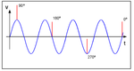
The phase angle is the degree on the AC sine wave where the surge is placed. This can be selected either via the front panel display or software and is commonly required at 0, 90, 180, and 270 degrees. This is applied to both negative and positive pulses as well as a variety of different coupling paths. If using preprogrammed routines these will likely already be included in the test settings. The image on the left illustrates the placement of surges on an AC sinewave at corresponding angles.
Coupling Paths/Configurations
The coupling configuration or path is which line(s) the high and low outputs from the generator are connected. Two main surge standards provide the coupling requirements IEC 61000-4-5 and ANSI C37, with the ANSI standard having a common mode requirement, where 2 lines are surged simultaneously to ground.
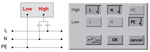
The associated simplified diagram illustrates Line and Neutral to Earth configuration. The different paths can be selected under the coupling decoupling network (CDN) commonly found under the combination surge menu. When conducting testing, many generators offer preprogrammed test routines allowing for the required configurations to be tested in relation to the standard.
Direct Injection Testing
Test using direction inject is accomplished by using the direct pulse outputs commonly labeled HV and COM. This is commonly done for some telecommunications tests as well as other tests where EUT will likely not be powered up when experiencing surges.
Direct injection is a power-off test!
Testing using the direct pulse output out while EUT is powered on will cause damage to the surge generator. The direct out should not be connected to any power conducting lines.
Using a Surge Generator for Data or Communication Lines/Ports
Surge testing for data or communications ports is accomplished for unshielded lines using a CDN, for shielded lines the surge is applied directly to the shielding. Line synchronization as we discussed for power lines isn't an issue with data lines allowing for most data line CDNs to be used with a variety of generators so long as the right connections are made.
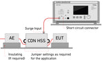
The associated image illustrates how a typical setup with the Teseq CDN HSS-2 is setup with a transient generator to conduct testing. Data line CDNs are designed for a particular number and type of lines, either unsymmetrical or symmetrical, the CDN HSS-2 in the example is designed for up to 4 symmetrical pairs.
These surge injection devices typically either provide individual communication line inputs or adapters such as the RJ45. These devices are designed in accordance with IEC 61000-4-5 designed 1.2/50uS surges, some models such as the EMC Parter CDN-UTP8 provides capabilities for ringwave tests in accordance with IEC 61000-4-12 and 10/700uS surges as well.
Pulse/Waveform Verification
Verifying the waveforms of surge generators is commonly done both on a regular basis and during calibration. This is done by verifying the voltage (open circuit) or current (closed circuit) waveforms in accordance with the underlying standard.
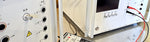
Current Waveform
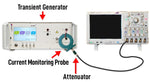
Combination wave surge current waveforms are verified closed circuit across different CDN Lines. The image on the right shows the verification of L1 to Neutral current waveform using the Haefley Axos 5.
During this verification, no EUT power is used otherwise damage to the measuring equipment will likely occur.
Commonly verification will require a oscilloscope, current monitoring probe (commonly Pearson 110), and an attenuator. Calibrated measurement equipment is often used for ISO 17025 calibrations, however, it may not be required for verification of functionality.
Voltage Waveform
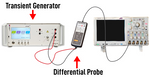
Voltage waveform verification is done using a voltage differential probe comparing to values set values typically provided from a previous calibration. This is done with both combination wave surges, electrical fast transients as well as other voltage based EMI events.
The most commonly used differential probe is the Cal Test CT3681, which provides capabilities for up to 7kV. There are also additional probes on the market place that offer capabilities above 15kV.
Surge Generators FAQ
Surge generators are testing devices used to produce fast rise time, short duration waveforms commonly used to replicate both indirect lightning and power grid switching transients on data or power lines.
The EFT immunity tests purpose is to ensure products are designed rugged enough to withstand fast transients commonly caused when an AC/DC connection is made or broken, equipment powered down, or circuit breakers switched.
A surge generator is a device used to test an EUT's ability to withstand power grid switching and indirect lightning transmitted down data or power lines.
References:
AN4275 Application note - IEC 61000-4-5 standard overview. (n.d.). In STMicroelectronics (DocID024389 Rev 1). STMicroelectronics. Retrieved March 31, 2023, from https://www.semiee.com/file/backup/STMICROELECTRONICS-AN4275.pdf
D. (2020, October 17). Data Line CDNs. HV Technologies. https://www.hvtechnologies.com/data-line-cdns/
Surge Generator | EM TEST | Teseq. (n.d.-b).https://www.ametek-cts.com/products/productgroups/transient-generators-surge-and-burst/surge-generator
