Electrical Transients - Sources, Waveforms, & Mitigation Tips
Electrical Transients
Electrical transients cover a wide range of interference and have the potential to impact the operation of electrical systems and equipment. These events can be caused by power grid switching, sudden disconnection or connection, lightning, as well as generated within or by associated electrical equipment. They commonly impact commercial, automotive, and military, electrical systems and equipment, and are often transmitted by power and data lines.
What are Electrical Transients?
Electrical transients are fast risetime, short duration energy pulses that commonly have voltage and current components often transmitted down data or power lines. Common causes of power line transients are when an AC/DC connection is made or broken, equipment powered down, or circuit breakers switched.(1)
Transients can be broken down into two main categories: impulses and oscillatory.(2)The associated image shows each common type of transient, an electrical fast transient (EFT) in accordance with IEC 61000-4-4 and a ring wave transient in accordance with IEC 61000-4-12. The IEC 61000-4 series of standards are some of the most commonly used requirements for defining these events and will be referenced throughout the article.
These potentially high voltage and current events typically have failures categorized by hard and soft failures, with complete degradation of function being considered a hard failure. A soft failure can be remedied by recycling the power to the equipment. It is crucial that the design of electrical systems be sufficiently immune, having no impact on the operation, to ensure both product reliability and compliance to underlying standards.
Internal and external sources of transients
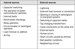
This type of conducted electrical interference can come from both internal and external sources which has the potential to impact AC and DC systems. The associated table provided by Cadence System Analysis(3) specifies common sources of electrical transients. It is estimated that between 60-80%(4) of surges, a common transient, are created within a facility as opposed to externally.
There are many potential sources of these events and the waveforms used to simulate these events can vary significantly. It is also worth noting that how the associated transient is defined can vary by application and the underlying standard.
Related Standards
There are a variety of both international and manufacturer-based standards that are used to describe, define, and test the impact of transients on equipment. The most commonly used commercial requirements include the IEC 61000-4 series as well as CE Mark and the ANSI/IEEE C series. The breakout below shows the most common sections and the associated transient waveforms.
IEC 61000-4-4 - Electrical Fast Transients (EFT)
IEC 61000-4-5 - Combination Wave Surges
IEC 61000-4-12 - Ring Wave Impulses
ANSI/IEEE C62.41 - Combination Wave Surges
ANSI/IEEE C37.90.1 - Damped Oscillatory Wave (DOW)
Power Line Transients
Transients can be transmitted down electrical paths from device to device having the potential to impact a large amount of electrical equipment. Given the wide number of potential culprits, waveforms used to characterize these events also can vary widely based upon the application and anticipated environment.
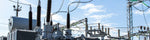
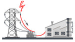
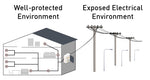
The severity of transients can also vary by the environment in which the equipment will operate, with the most exposed and industrial often being the harshest. The associated image illustrates how an outdoor environmental event has the potential to impact and travel to the corresponding grid and subsequent locations.
These types of conducted interference events can produce many different pulse shapes, however they are generally categorized by impulse transients and oscillatory transients. Both types of transients are not exclusive to power lines and can also be transmitted via data or communication lines.
What are Impulse Transients?
Impulse transients are fast increases in voltage and/or current characterized by a primarily positive or negative polarity with durations generally less than 1 millisecond.
Impulse Transients
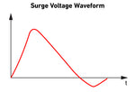
Impulse transients are commonly described in a rise time by duration maximum value format. The associated voltage pulse based upon the generic wave shape based on IEC 61000-4-5 could be described as 1.2us/50us voltage waveform followed by the associated peak voltage. As can be seen in the associated image, there is a large decrease in the maximum value following the initial pulse which is typical among impulse transients.
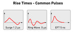
When evaluating rise times of impulse transients, it is common to see that waveforms with faster rise times have a shorter duration. Compare the pulse above 1.2us by 50us to an electrical fast transient pulse (IEC 61000-4-4) which is 5ns by 50ns.
When impulse transients have both voltage and current waveforms associated with them, they are commonly referred to as combination wave pulses. These combination wave pulses are included in the surge requirements in IEC 61000-4-5, CE Mark, and ANSI/IEEE test requirements.
What are Oscillatory Transients?
Oscillatory transients are rapid changes in voltage typically characterized by fast risetime and switching of polarity "ringing" decreasing in value each cycle.
Oscillatory Transients
Oscillatory transient pulses are momentary changes in voltage and/or current where polarity rapidly changes while values decay. These type of transients are commonly broken down by high, medium and low frequencies.
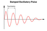
The associated image helps to illustrate a general wave shape associated with oscillatory transients. The oscillation or "ringing" can be seen as the value of the pulse decreases over time. This waveform, based off the generic waveform according to IEC 61000-4-18, has the Toscillation indicated, which can vary based upon the underlying requirements.
The three different frequency categories for oscillatory frequencies each represent EMI occurrences in the environment where the equipment is planned to operate. The frequencies for common IEC oscillatory pulses span from 100 kHz to 30 MHz including all three categories.
Waveform Characteristics of Transients
While there are many different characteristics that can be used to describe electrical transients, most are referenced by rise time, peak value or test level, duration/oscillation components. These are not the only factors used to describe these waveforms, others are also used, additional information can be found in IEEE 1159-2019. Generally speaking, reference to a particular standard or requirement will also be included further describing the pulse and compliance to a particular requirement.
Rise Time
The rise time of a particular waveform can be thought of as the time it takes to move from 10% to 90% of the front rise of the waveform. Rise times are typically determined by the underlying test requirement or standard and are commonly in the nanosecond to millisecond ranges.
The associated image illustrates some of the common electrical transient waveforms and voltage (open circuit) rise times consistent with IEC requirements. Rise times for the current (closed circuit) waveforms can also have requirements for some pulses, most commonly combination wave surges.
Duration
The voltage waveform/pulse duration for common transients is commonly thought of as the time between the 50% on the front risetime of the pulse to the 50% fall time of the pulse. The exact methodology for how the value is determined can vary by standard, with current waveform duration requiring additional considerations in accordance with IEC 61000-4-5.
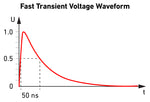
The associated image shows a single electrical fast transient pulse, unlike many other pulses, the testing is done in rapid sessions or bursts. This can provide confusion in differing from pulse duration and burst duration as burst would indicate a series of pulses both of which have
Peak Value/Test Level
The peak or maximum value is commonly used to describe both oscillatory and impulse transients. Given that other criteria of the waveform remain the same, the peak values typically vary by test level. The pulses are typically described by the rise time, duration, and peak value which is correlated to a particular level.
The most common criteria associated with a particular test level is the relative amount of exposure of the anticipated operational environment of the equipment under test (EUT).
The most protected or electrical isolated environments are likely to have less severe EMI exposure warranting a lower threshold of testing. This can vary based upon the pulse or standard, which can have specific condition requirements and levels.
Polarity
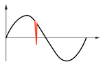
While not as common initially describing transients, these pulses can be both negative and positive in polarity. Typically while testing equipment a series of both positive and negative pulses are used to replicate real world events.
The associated image shows how the negative pulses are added to a sine wave at varying degrees. The exact placement of these pulses at the associated degrees are determined by the underlying standard or associated test plan.
What causes electrical transients?
Electrical transients can be caused by capacitive coupling, inductive coupling, or conducted noise often generated by a device or sub-circuit.
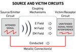
Transient Culprits & Coupling
These noise transients are able to affect power / ground circuits and signal / data circuits. The effect is through electrical or magnetic coupling mechanisms by the source conductor, which is carrying the transient, and the victim conductor being affected by the transients of the source conductor and through conductive and radiated coupling into a unrelated system from a “noisy” source system.
There are three basic noise mechanisms for coupling transient noise into target electrical systems/subsystems/printed circuit board or board traces.
Capacitive and inductive noise coupling are referred to as generating near field noise since the effect is highest at relative short distances between conductors inside the equipment where the coupling occurs, however energy from these couplings mechanisms can also radiate as far-field electromagnetic fields (EM fields) outside of the equipment generating the noise. Also, conductive noise are direct transfers of unwanted noise through cabling from one equipment into unrelated equipment.
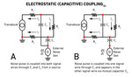
Capacitive Coupling
This is a voltage based effect also called the coupling of electrostatic noise. Electrostatic noise is experienced whenever conductors are exposed to a time varying electrical (E) field and a voltage is induced. Any pair of conductors separated by an insulating material (including air) constitute a capacitor. The amount of capacitive coupling between source (aggressor) conductor and victim conductor is a function of the mutual capacitance C between both conductors, the strength of the electric field in the aggressor conductor and the victim conductors impedance to ground.
The current induced from the E field of the aggressor into the victim is given by i = C *(dv/dt) where C is the value of the mutual capacitance between both conductors and dv/dt is the rate of change of the voltage in the source conductor. The voltage that results from this induced current will depend on the victim conductors impedance to ground.
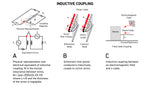
Inductive Coupling
This is magnetically coupled noise which affects the current flowing in a conductor. The rate of change of current flowing in the source (aggressor) conductor can affect the current in an unrelated or same conductor a distance away via the aggressors magnetic (M) field. The aggressor conductor acts like a transformer primary with the victim conductor it secondary.
The amount of inductive coupling increase with higher and faster rate of change of current flow, proximity of the source conductor to the victim conductor, and geometry of conductor (round diameter conductors are more efficient at coupling vs flat conductors). The voltage induced into a victim circuit is given by v=M*(di/dt ) where M is the mutual inductance and di/dt is the is the rate of change of current in the source conductor.
Conducted Noise
This noise, also called conducted EMI is unintentional energy generated by a device or sub-circuit. This type of noise is transferred to another device or sub-circuit via signal cabling, power or ground planes to nearby victim equipment which results in unwanted signaling (noise) as opposed to #1 and #2 above which is transferred through air or another isolation medium.
Troubleshooting Tips/Fixes
E & M Field Coupling
The following are rules of thumb to improve or make the effect better or worse:
- Both are directly proportional to aggressor frequency, doubling the frequency of aggressor doubles the effect on the victim.
- Both effects are reduced if aggressor and victim are spaced further apart, this reduces the mutual capacitance/inductance.
- For M field coupling, doubling the resistance of the aggressor nearly halves the effect on the victim.
- Both mutual coupling effects are reduced by bringing the conductors closer to their return path plane.
- For E field, higher aggressor voltage implies larger victim effect; lower aggressor voltage implies a lesser victim effect.
Effects on transient induced noise:
- On digital/analog system the effects can disturb the system’s operation or cause a non-recoverable failure. Whenever these effects occur and their magnitudes and durations are above a threshold where these transients are detected by an operating system, the system will respond with erroneous results which may cause:
- On power systems the effects similarly can affect the systems operation in the following manner:
Methods to mitigate the effect of transient induced noise:
- On digital/analog systems the effects can be mitigated in the following manner:
- On power systems the effects are created by transient/surges caused by switching equipment and most often lightning surges, these effects can be can be mitigated in the following manner:
Electrical Transients FAQ
The two types of electrical transients are impulsive and oscillatory.
Voltage transients are fast risetime, typically short duration increase in voltage which are commonly transmitted via power or data lines.
Transients commonly occur in electrical circuits because of capacitive coupling, inductive coupling, or conducted noise.
References:
1)Koeppen, P. (n.d.). Electrical Fast Transients (EFT)/Burst ESD Details. Electrical fast transients (eft)/burst ESD details. Retrieved September 6, 2022, from http://www.esdunlimited.com/eft.html
2)DeDad, J. (2006, March 1). Understanding Transients: A Primer. EC&M. Retrieved September 5, 2022, from https://www.ecmweb.com/archive/article/20894068/understanding-transients-a-primer
3)Cadence System Analysis. (2022, February 2). Everything You Need to Know About Transients Electrical Circuits | System Analysis Blog | Cadence. Cadence. Retrieved September 5, 2022, from https://resources.system-analysis.cadence.com/blog/msa2022-everything-you-need-to-know-about-transients-in-electrical-circuits
4)What Are Surges | NEMA Surge protection Institute. (n.d.). Retrieved September 7, 2022, from https://www.nemasurge.org/history/
5)Csanyi, E. (n.d.). 4 ways in which noise can enter a signal cable and its control. Electrical Engineering Portal. Retrieved September 14, 2014, from https://electrical-engineering-portal.com/4-ways-in-which-noise-can-enter-a-signal-cable-and-its-control-part-1
AllumiaX LLC. (2022, January 23). Electrical Transients in Power Systems. Retrieved October 9, 2022, from https://www.allumiax.com/blog/electrical-transients-in-power-systems
IEEE 1159-1995. Recommended Practice For Monitoring Electric Power Quality. New York: IEEE, Inc.
Rogers, B. (2005). An Overview of Power Quality Issues.
Electrical Noise and Transients. (2022, March 23). Fluke. Retrieved October 9, 2022, from https://www.fluke.com/en-us/learn/blog/power-quality/electrical-noise-and-transients
IEC 61000-4-4:2012 RLV – “Electromagnetic compatibility (EMC) - Part 4-4: Testing and measurement techniques - Electrical fast transient/burst immunity test".
IEC 61000-4-5:2014– “Electromagnetic compatibility (EMC) - Part 4-5: Testing and measurement techniques - Surge immunity test".
IEC 61000-4-12:2017– “Electromagnetic compatibility (EMC) -Part 4-12: Testing and measurement techniques - Ring wave immunity test".
Parcon, P. (n.d.). Oscillatory Transients Archives. APC UPS Blog - ExcessUPS.com. Retrieved September 7, 2022, from https://excessups.com/blog/tag/oscillatory-transients/
Power Quality World. (2011). OSCILLATORY TRANSIENTS IN THE POWER SYSTEM. Power Quality in Electrical Systems. Retrieved September 7, 2022, from http://www.powerqualityworld.com/2011/05/oscillatory-transients-power-system.html
Products, E. (1999, March 1). Ac line transients: The silent killer of power systems. Electronic Products. Retrieved September 7, 2022, from https://www.electronicproducts.com/ac-line-transients-the-silent-killer-of-power-systems/