Magnetic Field Generators - Common Tests & Equipment
Magnetic Field Generators
Magnetic fields are present in a variety of different electrical environments including industrial, military, commercial, and medical. The ability of equipment to withstand the magnetic fields in the anticipated environment is important both for product reliability and compliance. There are a variety of sources of magnetic fields including RF transmitters and other wireless technologies that are becoming more common, increasing the amount of potential sources.
With the prevalence of magnetic fields, it's necessary to evaluate the impact they have on electronic equipment. The goal of these tests is to document any deterioration of function, ensuring the equipment's design is robust enough to be unaffected by these events.
What are Magnetic Field Generators?
Magnetic field generators are the equipment used to create magnetic fields in immunity testing environments. This will typically include a source, antenna, and measurement equipment that meet the underlying testing requirement.
Magnetic Field Test Equipment
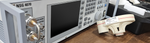
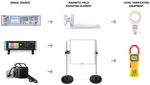
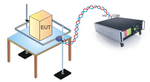
Equipment used in magnetic field testing will typically include an antenna, a signal source, as well as equipment used in the measurement/verification of the magnetic field level. The equipment will be determined by the underlying standard, test level, and method used. The below image illustrates common equipment used for creating the magnetic field for both commercial and medical immunity testing.
What is magnetic field testing?
Magnetic field testing is an immunity test where the equipment under test is exposed to predefined magnetic field levels to evaluate the potential impact it has on the operation of the equipment.
- Close Proximity Magnetic Fields - IEC 61000-4-39 & IEC 60601-1-2
- Power Frequency Magnetic Fields - IEC 61000-4-8
- Impulse & Oscillatory Magnetic Fields - IEC 61000-4-9 & IEC 61000-4-10
- Low-Frequency Susceptibility - MIL-STD-461 RS101
Close Proximity Magnetic Fields
The term “close proximity” generally refers to a separation distance between the source and victim circuit/equipment. When looking at IEC 61000-4-39 this distance is less than or equal to 200 mm for frequencies greater than 26 MHz. The distance is less than or equal to 500 mm for frequencies lower than 26 MHz.(1) At this time IEC 61000-4-39 only pertains to magnetic fields from 9 kHz to 26 MHz, from 380 MHz to 6 GHz a TEM horn antenna is used.
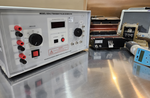
The associated video focuses on IEC 610004-39 testing using the Teseq NSG 4070 test system using the LAS 6120 and LAS 6100 antennas.
The NSG 4070 test system has several models that provide an all-in-one box solution for this testing which has a built-in amplifier, signal generator, and power meters. The video includes:
- Overview of the Test System & Antennas
- Included equipment with the Antenna Kits
- EM Test ICD.Control Software
- Running Test Level Calibration
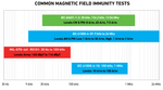
The two most common standards that test for immunity to close proximity magnetic fields are IEC 61000-4-39 and IEC 60601-1-2. Of these standards IEC 61000-4-39 pertains to to commercial products, whereas IEC 60601-1-2 focuses on medical equipment (ME). The test levels and a comparison below can be found in more detail at Absolute EMC Article "IEC 60601-1-2 Ed. 4.1 New Requirement, Immunity to Proximity Magnetic Fields".
Close Proximity Magnetic Field Test Equipment
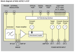
To conduct testing in accordance with either IEC 61000-4-39 or IEC 60601-1-2, the test system will be needed to generate the necessary magnetic fields to drive the radiating loop antennas to meet the field strength requirements. The designs for these systems vary by manufacturer, however, all typically include a signal generator, power amplifier, dual directional coupler, and power meters. It is also recommended to utilize software if available to streamline testing, or if selecting custom testing criteria.
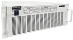
A block diagram of the Teseq NSG 4070C2-LFCP can be seen below. This test system has a built in 100 watt amplifier from 9 kHz to 50 MHz as well as signal generators and power meters up to 1 GHz.
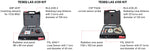
The other major component is the radiating loop antenna, along with the corresponding accessories needed to conduct both the calibration/test leveling. These are typically sold as kits as is the Teseq LAS 6120 (9 kHz to 150 kHz) and Teseq LAS 6100 (150 kHz to 30 MHz) which include the required spacer and monitoring probes used for testing. Both kits can be seen in the associated image with the included accessories labeled.
Conducting Testing to IEC 61000-4-39
It is necessary to run a test leveling/calibration prior to beginning testing. Below you will find the steps for both the leveling, as well as conducting testing for the LAS 6100 antenna for the entire frequency range of 150 kHz to 30 MHz.
Test level setting (calibration) setup for the entire frequency range
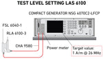
- Connect the amplifier output via the RF cable CHA 9580 to the transmitting antenna.
- Move the receiving antenna to the 5 cm distance from the transmit antenna using the spacer.
- Connect the receiving antenna with the BNC cable to the power meter channel 1 of NSG 4070C1/C2-LFCP
- Configure the test parameters in the software. Avoid damaging the power meters by calculating the expected levels beforehand. Use attenuators if necessary. Use the valid correction factors for the receiving antenna.
- Perform the test level setting procedure saving the result
Test setup for the entire frequency range
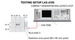
- Connect the amplifier output via the RF cable CHA 9580 to the transmitting antenna.
- Remove the receiving antenna and place the radiation area panel at a distance of 5 cm from the transmitting antenna using the spacer
- Recall the test parameters and calibration result in the software.
- Perform the test.
Power Frequency Magnetic Fields
Power frequency magnetic fields are commonly tested in accordance with IEC 61000-4-8 and focus on industrial and household environments as well as electrical substations. As the name implies, these magnetic fields are aligned with power-line frequencies typically either 50 Hz or 60 Hz. The required test equipment will depend on the equipment under test (EUT), test level, and duration of the test (continuous or short).
What are power frequency magnetic fields?
Power frequency magnetic fields are those magnetic fields which are at a frequency of 50 Hz or 60 Hz which can be generated in extreme levels near railway installations, substations, or power plants.
IEC 61000-4-8 testing is intended to demonstrate the immunity of equipment when subjected to power frequency magnetic fields related to the specific location and installation condition of the equipment (e.g. proximity of equipment to the disturbance source). The power frequency magnetic field is generated by power frequency current in conductors or, more seldom, from other devices (e.g. leakage of transformers) in the proximity of equipment.(2)
IEC 61000-4-8 Testing
Testing for IEC 61000-4-8 is conducted either with a continuous magnetic field or a short-duration magnetic field (between 1 and 3 seconds). These levels can vary based on the different anticipated electrical environments, with class 5 being the highest relating to severe industrial environments.
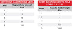
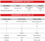
The associated test levels for both continuous and short duration requirements provided by RF EMC Development can be seen on the right. IEC 61000-4-8 doesn't define individual test levels for specific products, which can be found in generic or product specific standards.
Power Frequency Magnetic Field Generators & Equipment
To generate these fields in a testing environment, an inductive coil antenna is used to propagate the field. There are three different categories of inductive coils used for testing: standard 1 meter by 1 meter or 1 meter by 2.6 meter coils, and other non-standard inductive coils. The most common coil is a 1 meter by 1 meter, however it is dependent on the size of the equipment under test. The 1 meter by 1 meter antenna and 1 meter by 2.6 meter antenna are standardized, and do not require verification of the magnetic but the current going through the coil.
To achieve the required levels of current through the coil a current transformer or other external device may be needed depending on the test level. For higher level testing towards the 100 A/m range more specialized equipment will be needed. Some transient generators offer capabilities for low-level testing, however, in many situations external equipment is needed.
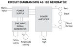
The most common of these generators are the EM Test MFG 40-100, EM Test MFT 100, as well as the Haefely MAG 1000 System. The image on the right is the circuit diagram from the MFG 40-100 that illustrates the concept behind the generator.
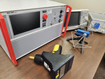
The associated video focuses on the EM Test solution for the short-duration power frequency magnetic field test test which has levels of up to 1000 A/m.
This video includes information on the requirements of IEC 61000-4-8 as well as using the Ametek CTS MFC 1000.1 and MFT 100.
- Overview EM Test System
- Connections & Setup of Equipment
- MFT 100 V/I Characteristics
- Measurement Equipment
Impulse & Oscillatory Magnetic Fields
Both impulse and oscillatory magnetic field testing to IEC 61000-4-9 and IEC 61000-4-10 are conducted using a transient generator along with an appropriate coil. These magnetic field tests use transient waveforms as the underlying events that drive the associated magnetic fields via the coil. These tests are not as common as power frequency magnetic fields, but depending on the application, they can be required.
The image below provides the different test levels required for both IEC 61000-4-9 and IEC 61000-4-10 testing provided the by MFT1000.1 user manual.
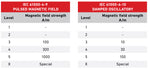
Both of these requirements can be met using the same coil and a transient generator as a signal/waveform source. For these tests separate transient generators are used as capabilities for combination wave surge and damped oscillatory waveforms aren't typically provided in the same system.
Impulse Magnetic Fields
IEC 61000-4-9 testing is commonly accomplished by using the current output from a combination wave surge generator as the standard specifies an 8us by 20us waveshape. This immunity requirement is designed to replicate magnetic disturbances in industrial installations, power plants, railway installations, and substations.
Depending on the manufacturer, this capability will already be added on the transient generator, or it could require an access code. Some older generators could require an additional 18 uF capacitor, that is in series with the coil antenna. Many newer surge generators already have a built-in 18 uF capacitor.
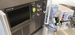
An example of the setup using the EM Test NX5 and MFC 1000.1 can be seen in the associated image. This test can be run either through the front panel display or via the control software.
Oscillatory Magnetic Fields
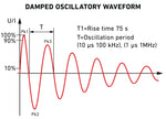
Damped oscillatory magnetic fields are mainly related to the operation of high voltage bus-bar isolators. As with the impulse magnetic field test, a transient generator is used to provide the required waveform. This standard has the same waveform requirements as the slow pulses (100 kHz and 1 MHz) of IEC 61000-4-18 allowing for the same generator to be used for oscillatory immunity tests.
The associated image illustrates a damped oscillatory waveform meeting the requirements of both IEC 61000-4-18 and IEC 610000-4-10. The setup for this test is very similar to that of IEC 61000-4-9 with current peak value, damping, and oscillation frequency waveform characteristics verified.
MIL-STD-461 RS101 - Radiated Susceptibility Magnetic Fields
RS101 is a military-based requirement for magnetic field testing that covers 30 Hz to 100 kHz using either a radiating loop or alternatively a Helmholtz coil to generate the field. This standard is applied only to specific equipment, including ground equipment near minesweeping or with mine detection capabilities, as well as others in section 5.20.1. The only grouping present in Table 5 completely covered is Army aircraft. This standard is free to download from the DOD, which can be accessed by clicking here.
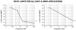
This standard provides two different sets of test level criteria for both Navy and Army applications, with Army starting higher at 180 dBpT. The Navy RS101 limit from 30 Hz to 2 kHz was derived from the worst case magnetic field radiation from a power transformer (~170 dBpT) and applicable cable types (DSGU-400), and takes into account the user equipment power line harmonic content and maximum anticipated power consumption. The Navy RS101 limit above 2 kHz is based on the measured magnetic field environment of Navy platforms. The Army has maintained the basic relationship of the RS101 and RE101 limits having the same shape.(3) The limit levels for both Army and Navy are shown below in dBpT.
Test Equipment
As with other magnetic field tests, measurements are required during the calibration procedure. This is accomplished using a loop sensor with adjustments made for the antenna factor. There are three main manufacturers that make radiating loops designed for RS101 testing, the Schwarzbeck FESP 5132, Solar 9230-1, and Com-Power Mil-Std Loop Antenna Set. A simplified list of required equipment for both the radiating loop and Helmholtz coil is shown below.
RS101 Test Equipment (5.20.3.2 & 5.20.4.2)
- Signal Source
- Radiating loop/Helmholtz coil
- Loop Sensor
- Receiver or Narrowband Voltmeter
- Current Probe
- LISNs
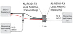
The loop sensor is used to measure the field from the loop or coil during the calibration procedure. During the calibration, both a current probe and measurement receivers are used following figure RS101-3, of which an example is shown using Com-Power equipment. Verification data of the calibration of the radiating loop will be saved for the report later.
Once the calibration has been completed, testing can begin by properly placing the the loop sensor while generating the associated magnetic field using a scan rate not exceeding Table III. The magnetic field strength during testing should be at least 10 dB greater than the limit but not exceeding 15 Amps. Any deviation or susceptibility will be noted along with the corresponding frequency.
Magnetic Fields Generators and Testing FAQ
The test report for IEC 61000-4-39 is the document which is provided upon the completion of testing that describes the testing and any impact on the equipment under test (EUT).
The frequency for IEC 61000-4-39 magnetic field testing is 9 kHz to 150 kHz and 150 kHz to 26 MHz.
References:
Adamczyk, B. (2017, September). Current Probe Measurements in EMC Testing - In Compliance Magazine. In Compliance Magazine. https://incompliancemag.com/current-probe-measurements-in-emc-testing/
AMETEK CTS | NSG 4070C1. (2019). Ametek-Cts.com. https://www.ametek-cts.com/products/brands/teseq/nsg-4070c1
Application. (2025).Current Probe For Emissions Measurement | Com-Power Corporation. Com-Power.com. https://www.com-power.com/products/current-probes/emissions-current-probes/clce-400
Mee, S. (2018, June). Bulk Current Injection (BCI) – Substitution Method and Closed-Loop Method with Power Limitation - In Compliance Magazine. In Compliance Magazine. https://incompliancemag.com/bulk-current-injection-bci-substitution-method-and-closed-loop-method-with-power-limitation/
Samuels, T. (2023). Bulk Current Injection Testing. Ahsystems.com. https://www.ahsystems.com/notes/bulk-current-injection-test.php