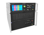
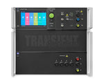
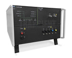
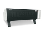
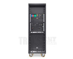
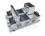
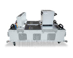
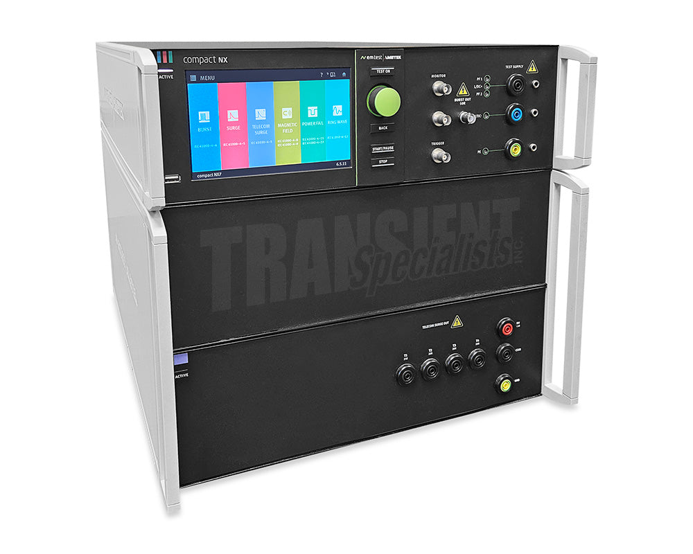
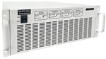
EM Test NX7 bsprt-1-400-32 - Front Side
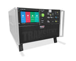
EM Test NX7 bsprt-1-400-32 - Front
EM Test NX7 Telecom Overview Video
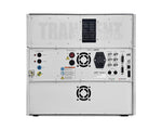
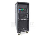
EM Test NX7 bsprt-1-400-32 - Back
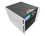
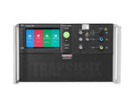
EM Test NX7 bsprt-1-400-32 - Front Side Above

EM Test NX7 bsprt-1-400-32

Rent Telecom Transient Generator

In Stock & Ready To Ship
Orders by 3pm ship today

The EM Test NX7 bsprt-1-400-32 is a multifunction telecom transient generator supporting 7 kV surge, 10/700 µs telecom surge, ring wave, and 5.5 kV EFT testing with an integrated 32 A CDN.

Features

  • 7 kV Surge, Ringwave, Telecom Surge, & 5.5 kV EFT
  • Built-in single phase CDN Max 400 V/32 A AC or DC
  • 400 Volt Model: bsprt-1-400-32
  • 10 us/700 us Telecom Surge to 7 kV
  • Current ISO 17025 Accredited Calibration
Up to 4 Free Days of Transit Time
Two transit days each way are excluded from rental period
  • Conducted Immunity System
  • Laptop with Charger
  • Power Cord
  • ESC EUT Supply Cable
  • ESA1.6 EUT Supply Adapter
  • SWL AD Warning Lamp Adapter Interlock
  • SCC AD Short Circuit Interlock 
  • Ethernet Cable
  • Software on USB Stick 
  • Software License 
  • UOC Optical Converter USB to LWL 
  • 5. Orange Fiberoptic Cable 
  • Printed Manual
  • Calibration Documentation 
  • EFT Ground Strip
  • Case
  • Can't find something? Contact Us

Description 

The compact Next Generation NX7 is the most versatile tester to address transient and power fail requirements for both international and commercial standards.

Featuring an easy-to-use color touch screen, the NX7 provides an economical solution for pre-compliance immunity testing as well as full-compliance testing and CE Marking. Its internal single-phase Coupling/Decoupling Network (CDN) can be extended for testing three-phase EUTs by means of an automatically controlled external CDN up to 200 A per phase. AMETEK CTS supplies a large range of accessories for various applications such as magnetic field tests and more.

Benefits:

The compact NX7 is a standalone generator which includes everything necessary to perform fully compliant tests. With separate power mains supply inputs, it allows the utilization of different EUT supply voltages for maximum flexibility.

The NX7 can be operated manually from the intuitive front touch screen or remotely via its built-in Ethernet, USB or optical interface. Failure inputs allow control of an ongoing test sequence based on the state of the EUT. Monitoring outputs (BNC) offer easy signal verification and measurements. For enhanced safety requirements, features like interlock and a warning lamp are available.

NX7 is the first generator that recognizes the connected EUT power configuration. Only coupling selections to active lines are enabled. Non existing lines will be disabled from the menu settings. Pre-programmed routines with common Test Standards allow maximum user convenience. Quick Start Test routines where parameters can be changed during susceptibility level evaluation are also available.

Operation:

An innovative color touch screen with intuitive menu structure and defined keys for Start / Stop / Break, indicated by LED bars, enables the user to program test routines quickly and accurately. The touch screen and knob allow fast control of all test parameters of the programmed routine, ensuring that test procedures are simplified and confidence is high that every step is carried out correctly.

Software:

Outstanding user convenience, clearly structured windows and operation features, EM TEST's comprehensive standards library along with the flexibility to easily generate user specific test sequences are the main features of iec.control software. The software will be automatically configured in accordance with the connected EM TEST generators. Extensive reporting capabilities help the user to create test reports that meet international requirements.

The iec.control is supported by Windows 7, Windows 8 and Windows 10. Remote control is achieved either via Ethernet or optical interface with USB connector at the PC side. The iec.control supports various interfaces for the communication to external measuring devices

Technical Details
Electrical Fast Transients:
Burst Module
As per IEC/EN 61000-4-4 and EN 61000-6-1, -6-2
Test voltage
200 V - 5,500 V+/- 10%;
100 V - 2,750 V +/- 10% into 50 ohm
Pulse shape
5/50 ns into 50 ohm and 1,000 ohm
Rise time tr
5 ns +/- 30% into 50 ohm;
5 ns +/- 30% into 1,000 ohm
Pulse width td
50 ns +/- 30% into 50 ohm;
50 ns -15/+100 ns into 1,000 ohm
Source impedance
50 ohm
Polarity
Positive, negative
Trigger Circuit:
Trigger of bursts
Automatic, manual, external
Synchronization
0 - 360 degrees, resolution 1 degree (16 - 500 Hz)
Burst duration (td)
td = 0.10 ms - 9,999 ms
Repetition rate (tr)
tr = 10 ms - 9,999 ms
Spike frequency
f = 1 Hz - 1,000 kHz
Test duration
T = 0:01 min - 99:59 min
T > 99:59 min --> endless
Outputs:
Direct
Via 50 ohm coaxial connector
Coupling mode
L, N, PE; all combinations
EUT supply
AC: 300 V / 400 V, 50/60 Hz
DC: 300 V / 400 V,
Current: 16 A / 32 A
CRO trigger
5 V trigger signal for oscilloscope
Test Routines:
Quick Start
On-line adjustable parameters, easy-to-use
Standard Test routines
As per IEC/EN 61000-4-4, Levels 1 - 4
As per IEC/EN 61000-6-1, -6-2
As per ECE R-10 Rev5
Extended Test routines
Change voltage after T, Frequency sweep within one burst, Frequency sweep with constant number of pulses, Frequency sweep with constant burst duration, Synchronous burst release, Random burst release
Combination Wave:
Surge Module
As per IEC/EN 61000-4-5 and IEC/EN 61000-6-1, -6-2
Voltage (o.c.)
200 V - 7,000 V +/- 10%
Pulse front time
1.2 us +/- 30%
Pulse duration
50 us +/- 20%
Current (s.c.)
Max. 3,500 A +/- 10%
Pulse front time
8 us +/- 20%
Pulse duration
20 us +/- 20%
Polarity
Positive, negative, alternate
Trigger Circuit:
Release of pulses
Automatic, manual, external
Synchronization
0 - 360 degrees, resolution 1 degree
Repetition rate
max. 1 Hz (1 s - 9,999 s)
Event counter
1 - 99,999, selectable
Outputs:
Direct
Via HV connectors for external coupling networks
Coupling mode
Line to line
Line(s) to ground
EUT supply
AC: 300 V / 400 V, 50/60 Hz
DC: 300 V / 400 V,
Current: 16 A / 32 A
CRO trigger
5 V trigger signal for oscilloscope
Measurements:
CRO U-monitor
10 Vp at 7,000 V
CRO I-monitor
10 Vp at 3,500 A
Peak voltage
7,000 V in the touch display
Peak current
3,500 A in the touch display
Overcurrent protection
Breaks the Surge test when the surge current is over the limit, Limiter for differential mode, Limiter for common mode
EUT current
RMS current, Range 50 A, < +/-5%
EUT overcurrent protection
Breaks the test when the EUT current is over the limit,
Test Routines:
Quick Start
One-line adjustable parameters, easy-to-use
Standard Test routines
As per IEC/EN 61000-4-5,
As per IEC/EN 61000-6-1,
As per IEC/EN 61000-6-2,
Manual Standard Test routine
Extended Test routines
Voltage iteration after n pulses, Angle iteration stepwise, Phase angle randomiteration, Change coupling after n pulses, Change phase angle after n pulses
Pulsed Magnetic Field
as per IEC/EN 61000-4-9 Test levels 100, 300 and 1,000A/m Test level continuously adjustable under Quick Start
Dips, Interruptions, Voltage Variations
Power Fail Module:
As per
IEC/EN 61000-4-11,
IEC/EN 61000-4-29 and
IEC/EN 61000-6-1, -6-2
Channel PF1/PF2
AC voltage: max. 300 V / 400 V
AC current: max. 16 A / 32 A
DC voltage: max. 300 V / 400 V
DC current: max. 16 A / 32 A
Frequency
16 Hz - 500 Hz and DC
Switching time
> 1 us < 5 us into a 100 ohm resistive load (SVP 100)
Inrush current
> 500 A
Protection
Both channels are protected against short-circuit conditions.
Trigger Circuit:
Trigger of events
Automatic, manual, external
Synchronization
0 - 360 degrees, resolution 1 degree (16 - 500 Hz)
Repetition rate
10 ms - 9,999 s
Event duration
10 us - 99.999 s
Event counter
1 - 99,999, selectable
Outputs:
EUT terminals
L, N and PE
CRO trigger
5 V trigger signal for oscilloscope
Measurements:
EUT voltage (rms)
In the touch screen
EUT current (rms)
In the touch screen
MON V
Measurement of the EUT voltage, built-in divider:
300 V: 42,5:1, 10 V =425 Vpk,
400 V: 56.6:1, 10 V =566 Vpk
MON I
Measurement of the EUT current,
16 A: 7 A/V; 10 V =70 Apk,
32 A: 10 A/V; 10 V =100 Apk
Test Routines:
Quick Start
Standard Test routines
Extended Test routines
VoltAs per IEC/EN 61000-4-11 for AC supplies
As per IEC/EN 61000-4-29 for DC supplies
As per EN 61000-6-1, -6-2
Manual Standard Test routine
50/60 Hz magnetic field
As per IEC/EN 61000-4-8 Test levels 1, 3, 10 and 30 A/m with external current transformer MC 2630, Test levels 100, 300 and 1,000 A/m with external current transformer MC 26100
Ringwave
Ringwave Module:
As per ANSI/IEEE C62.41 and EN/IEC 61000-4-12
Test voltage
200 V - 7,000 V +/- 10%
Voltage
Wave shape (open circuit)
Rise time
0.5 us +/- 30% (first peak)
Oscillation frequency
100 kHz +/- 10%
Decaying
Peak 2 to peak 1 = 40 - 110% Peak 3 to peak 2 = 40 - 80% Peak 4 to peak 3 = 40 - 80%
Current
Wave shape (short circuit)
Rise time
0.2 us < tr <= 1.0 us
Oscillation frequency
100 kHz +/- 10%
Source impedance
12 ohm, 30 ohm, 50 ohm
Peak current
As per selected source impedance
Polarity
Positive, negative, alternate
Trigger Circuit:
Release of pulses
Automatic, manual, externa
Synchronization
0 - 360 degrees, resolution 1 degree
Repetition rate
max. 1 Hz (1 s - 9999 s)
Event counter
1 - 99,999, selectable
Outputs:
Direct
Via HV-safety lab connectors
Coupling mode
L, N, PE; line to line and line(s) to ground
DUT supply
AC: 300 V / 400 V, 50/60 Hz
DC: 300 V / 400 V,
Current: 16 A / 32 A
CRO trigger
5 V trigger signal for oscilloscope
Measurements:
CRO U-monitor
10 Vp at 7,000 V
CRO I-monitor
10 Vp at 3,500 A
Peak voltage
500 V - 7000 V in the touch display
Telecom Surge
Tsurge Module:
Test voltage (o.c.)
200 V - 7,000 V +/- 10%
Energy storage capacitor
20 uF
Polarity
Positive, negative, alternating As per ITU and ETSI recommendations
Front time
10 us +/- 30%
Pulse duration
700 us +/- 20% As per FCC part 68, Pulse B
Front time
9 us +/- 30%
Pulse duration
720 us +/- 20%
Output current @25 ohm output
5 A - 175 A (short circuit)
Rise time
5 us +/- 30%
Pulse duration
320 us +/- 20%, As per IEC 61000-4-5
Rise time
10 us +/- 30%
Pulse duration
700 us +/- 20%
Output current @25 ohm output
5 A - 175 A (short circuit)
Rise time
5 us +/- 20%
Pulse duration
320 us +/- 20%
Trigger Circuit:
Trigger of events
Automatic, manual, external
Repetition rate
max. 0.33 Hz (3 s - 999 s)
Event counter
1 - 99,999, selectable
Outputs:
As per ITU
For 2-wire T1/T2 with 25 ohm each
As per FCC part 68
For 2-wire T1/T2 with 25 ohm each
As per IEC 61000-4-5 Ed 3.0
For 4-wire T1/T2/T3/T4 with 25 ohm each
General Data
Interfaces:
Serial interface
2 x USB A for memory stick,
1 x USB B for service only,
Opto - Link to USB for remote
Lan
Ethernet for remote
Analog output
0 - 10 VDC to control an external transformer
Sys.link
26 pin high density connector to control an external coupling network
Fail inputs
EUT monitoring via input (one each)
EUT Monitor 1
EUT Monitor 2
Ext. Trigger
BNC Ext. Trigger IN pos slope 5 V
Ext. Sync Input
Differential input, 50 V - 690 VAC, 2 x 4 mm MC Safety connectors
Dimensions and Weight
16 A models
19"/6 HU, 500 mm deep, 19"/9 HU, with telecom module, approx. 30 kg
32 A models
19"/6 HU, 500 mm deep, 19"/9 HU, with telecom module, approx. 40 kg
Environment:
Temperature
10 C to 35 C (Operation) -10 C to 60 C (Storage)
Humidity
30 % to 70 %, non condensing
Atmospheric pressure
86 kPa (860 mbar) to 106 kPa (1,060 mbar)
Mains:
Supply voltage
85 V - 264 V
Frequency
50/60 Hz
Power
approx. 75 W
Fuses
115 V: 2 x 4 A slow blow,
230 V: 2 x 2 A slow blow
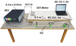
EFT/Burst Table Top Setup

When using the coupling clamp, the minimum distance between the coupling plates and all other conductive surfaces (including the generator), except the ground reference plane beneath the coupling clamp and beneath the EUT, shall be at least 0.5 m.

The test generator and the coupling network should be connected to the reference ground plane (acc. to high frequency requirements).
- The equipment under test must be isolated from the reference ground plane. The distance should be 10 cm.
Being part of the EUT, these requirements are also recommended for all connected cables. The EUT should only be grounded if this is recommended by the installation guideline. For safety reasons, the test without any ground connection should be conducted as well (at 100MHz 1 m ground cable lenght has an impedance of about 600 Ω)
- Whenever possible the test set-up and the cabling should always be the same; e.g. for testing power lines it would be possible to fix the cables on the test table for all tests in the same way.
- Lines under test and all other lines should be decoupled strictly.

Video Library

Video Guides
Related Videos

FAQs

This NX7 configuration combines telecom surge, combination wave surge, EFT/burst, ring wave, and power-fail testing. It supports multiple conducted immunity tests using one compact generator and built-in single-phase coupling decoupling network.

The telecom module generates the 10/700 µs voltage waveform required by common ITU, IEC, ETSI procedures, with an open-circuit output adjustable from 200 V to 7 kV.

For ITU and FCC Part 68 testing, the telecom module supports two-wire coupling through T1 and T2 with 25 Ω per line. It also supports four-wire T1, T2, T3, and T4 coupling for applicable IEC 61000-4-5 procedures.

The built-in single-phase coupling decoupling network supports EUT voltages up to 400 V AC or DC and currents up to 32 A. Pulses can be coupled to L, N, PE, and applicable line combinations.

Rent the EM Test NX7 bsprt-1-400-32

Weekly, two-week and monthly rentals available.

Questions?630-887-0329
EM Test IEC Test Equipment

Get the Right Accessories for Testing

Pair your rental EM Test NX5 or NX7 with compatible CDNs and accessories for mains, signal-line, and power-quality testing. We’ll help configure the equipment for your EUT and required test standard.

  • CDNs for testing 3-Phase EUT up to 125 Amps, 690 VAC
  • Capacitive Coupling Clamps for Testing I/O & Data Lines
  • Transformers and Variacs for Voltage Dips to IEC 61000-4-11

Accessories & CDNs for the EM Test NX5 and NX7

EM Test Coupling NX7 bsr-3-480-32 - Front Side

EM Test Coupling NX7 bsr-3-480-32 - Rent 3-Phase 32Amp CDN

  • Coupler for Surge, EFT, & Ringwave Pulses
  • Max 480 Volts 32 Amps AC
  • Automatic Coupler for NX5/NX7 Systems
  • CDNs for Power Lines Available up to 125 Amps
  • Current ISO 17025 Accredited Calibration
View Equipment
EM Test CCI - Front Side

EM Test CCI - Rent Capacitive Clamp EFT/Burst Testing

  • Construction as per IEC 61000-4-4 Ed.3
  • EFT/Burst Testing of Signal- and Datalines
  • Permissible Burst Voltage 7 kV
  • For Cable Diameter up to 40 mm
View Equipment
EM Test TVT 1-250-32 - Front Side

EM Test TVT 1-250-32 - Rent EM Test Tapped Transformer

  • Single Phase Automatic Step Transformer
  • Maximum 250 Volts 32 Amps
  • Designed for EM Test NX5 & NX7 Systems
  • Voltage Dips at 40 %, 70 %, 80 %, 100 %
View Equipment
Requesting Quote For
EM Test IEC Test Equipment
Need Help Choosing?

Our team can review your requirements and recommend the right equipment.

630-887-0329
info@transientspecialists.com

Request a Quote
Tell us what you need and our team will provide rental or purchase options.
No obligation • Fast Response