Surge Testing - Conducting Testing & Overview on Electrical Surges

Surge Testing
Surges are short-duration voltage and/or current transients that are transmitted down data or power lines commonly caused by switching and lightning events. We're going to focus on evaluating how surges are used to test electrical and electronic products ensuring no deterioration of function as well as meeting regulatory requirements.
Testing the robustness of the design of the equipment is accomplished by subjecting it to interference via power or data lines testing the corresponding ports on the equipment. This test falls under conducted immunity where unintended noise is transmitted via physical connection. Surges are defined in different ways depending on the industry and electrical environment.
We're going to focus on evaluating how they're used to test industrial and household electrical equipment. The associated video provides an overview on surge testing which includes:
- Overview of Electrical Surges & Testing
- Common Testing Requirements
- Surge Waveforms & Generators
What is Surge Testing?
Surge testing is the process where electrical equipment is subjected to quick, high-energy pulses transmitted via data or power lines to determine the impact it has on the operation of the equipment.
Causes of Electrical Surges
Surges are caused by the sudden release of energy stored via the switching of reactive loads such as electric motors or power factor capacitive banks. Surges can also be caused by insulation faults in AC power distribution networks where the energy is stored in the self inductance of long supply lines is released. Surges are also created by the indirect effect of lightning due to the induction of voltages and currents (or ground lift) as a result of the finite impedance in the grounding structure or from cables or metallic structures that are carrying the currents induced by lightning or the lightning bolt. Surges may also be caused by superconducting magnets which carry a great deal of energy which is released as a large surge when their field collapses due to loss of superconductivity.
The two main causes of electrical surges that we're concerned with are switching and lightning transients. The latter is the most commonly thought of cause of transients, where catastrophic damage can occur if the equipment is exposed to the energy of a strike. Switching is a much more common cause of surge than lightning transients(1).
Lightning can produce surges from:
- Direct lightning strikes injecting high current and producing voltages
- Indirect lightning strikes that induce voltages/currents on the conductors outside and/or inside a building
- Lightning ground current flows resulting from nearby direct-to-earth discharges coupling into common ground paths of the ground system of the installation. The rapid change of voltages and flows of current which can occur as a result of the operation of a lightning protection device can induce electromagnetic disturbances into adjacent equipment.
Power system switching can produce surges from:
- Major power system switching disturbances, such as capacitor bank switching.
- Minor local switching activity or load changes in the power distribution system.
- Resonating circuits associated with switching devices, such as thryristors
- Various system faults, such as short circuits and arcing faults to the grounding system of the installation.
Effects of Electrical Surges
Surges are high voltage and contain a significant amount of energy when when applied to electronic devices or their cables or printed circuit board traces and cause electrical/thermal overstress. Damage caused by surges are visible scorch marks, a visible spark or flash during a surge test, burnt or blown printed circuit board traces or components, burnt insulation, upsets in digital signals or analog signals.
Electrical Surge Transient Waveforms
Surge waveforms typically have a rapid increase reaching a peak value then a slower decrease until previous levels are reached. They are generally described by the rise time and duration/fall time for both the open circuit voltage and short circuit current (if applicable) as well as the associated peak test level. In conversation, the open circuit current component of combination wave surges might not be explicitly mentioned given that it is correlated to the peak voltage level.
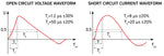
The associated image provided by the Ametek CTS IEC 61000-4-5 webpage illustrates both the current and voltage waveforms based on IEC 61000-4-5. Waveforms for the majority of surge requirements are in the microseconds and requirements can go as high as 30kV test levels for some applications. It's worth noting that the rise/front time and duration have tolerances as high as +/-30% having potentially significant differences between different waveforms of the same test level.
Depending on the different definitions of a surge, both impulse and oscillatory transients can be included. These include both the more common combination wave surges (including telecom) as well as ringwave (as in ANSI/IEEE C62.41.2-2002). For a more detailed description of electrical transients check out our post that spends more time on the waveforms by clicking here.
Oscillatory Transients
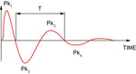
These transients are in some ways similar to that of combination wave surge (impulse transients) in that they have a rapid rise time and decrease, however unlike impulse transients, they have switches in polarity as the value decreases. The two most common requirements of these are damped oscillatory waves (IEC 61000-4-18) and ring waves (IEC 61000-4-12) which aims at replicating interference in low-voltage cable inducted by switching electrical grids and reactive loads(2). Similar to that of other surges, oscillatory transients can have both a voltage and/or current component depending on the underlying test requirement.
Surge Testing Standards
The majority of requirements designed for surge immunity testing are basic or generic standards that are often referenced by other product-specific requirements. The product-specific standard can reference either part or the complete underlying test requirement potentially including considerations for the specific application or equipment under test (EUT).
The test standards will vary in the definition of the waveforms, test levels, coupling methods, and impedance as well as other factors. There are also different requirements for particular applications including commercial, industrial, and military. Each electrical environment will present different conditions, leading to different test requirements.
The majority of our focus will be on the most common commercial standards, IEC 61000-4-5, ANSI 62.41.2, as well as IEC 61000-4-12. These standards share waveform requirements, however do have differences in coupling methods and test level.
IEC 61000-4-5
This requirement by the International Electrotechnical Commission is the most common surge immunity test which aims at replicating unidirectional surges caused by overvoltages from switching and lightning transients(2). This standard is currently in its third edition and recently included additional consideration for CDNs at different EUT current levels.
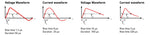
The two most common combination waveforms of this standard can be found below, the 1.2us by 50us waveform and 10us by 700us waveform tests. As mentioned previously these pulses are defined by a few different features, most notably the rise time and duration of both the open-circuit voltage and closed-circuit current waveforms. The images below illustrate both the combination wave surge pulses and the telecom surge pulse waveforms.
ANSI/IEEE C62.41
ANSI C62.41.1 and C62.41.2 are part of the C62 series of requirements on Surge Protection. This series of standards are American-based by IEEE and approved by ANSI. Per the IEEE Standards Association website, PC62.41.1 and PC62.41.2 are being developed covering the same content superseding the C62.41.1/2 requirements.
- ANSI/IEEE C62.41.1- Guide on the Surge Environment in Low-Voltage (1000V and less) AC Power Circuits
- ANSI/IEEE C62.41.2 - Recommended Pratices on Characterization of Surges in Low-Voltage (1000V and less) AC Power Circuits
This standard covers a variety of different surge waveforms including the combination wave surges and ringwave requirements. The different waveforms mentioned generally maintain consistency with the IEC series of requirements. In addition to surges, C62.41.2 includes mention of Electrical Fast Transient (EFT) in accordance with IEC 61000-4-4.
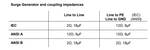
Another distinction between the ANSI/IEEE C62.41 and IEC 61000-4-5 requirements is the coupling path requirements for testing. The associate graph from the EM Test NX5 user manual illustrates the coupling impedance for both standards. These requirements are built into the design of the coupling decoupling network (CDN)associated with the transient generator.
IEC 61000-4-12
This test requirement for ring wave immunity is focused on low-voltage power cables as well as control and signal lines. While not as common as combination wave impulse transient testing, this surge requirement is included in many immunity test plans. As with the impulse surges, this oscillatory waveform includes both a voltage and current component both of which are required.
The ring wave is a typical oscillatory transient which is induced in low voltage cables due to the switching of electrical networks and reactive loads (loads made up of inductors and capacitors), faults and insulation breakdown of power supply circuits or lightning. This occurs in high voltage, medium voltage, low voltage power supply networks as well as in control and signal lines. This can occur in residential as well as industrial installations. The ring wave test is considered to apply more stress to the equipment being tested than the same level test under IEC 61000-4-5.
Conducting Surge Testing
Testing the impact surges have on electronic equipment is accomplished by injecting or coupling the associated waveforms on the cables going toward the equipment under. When conducting this testing the transient surge is injected on the cable, however the port on the EUT is the ultimate recipient.
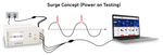
Power on testing is accomplished using a coupling decoupling network or CDN to inject the combination wave surge at the selected level and degree on the sine wave. The associated diagram illustrates the test concept where the transient is added to the AC sine wave going toward the equipment under test and any impact is monitored. Surge testing is also done on data or communication lines using a CDN designed for specific cable types.
While verification of the surge generator waveforms is not explicitly required in IEC 61000-4-5 before testing, it is highly recommended. Often times transient generators are calibrated on an annual basis to ensure the waveforms meet requirements, this is commonly done per ISO 17025 requirements. Given the nature of transient testing, periodic evaluations should be conducted of both the open circuit voltage and closed circuit current waveforms ensuring that the unit is functioning correctly.
A few steps can be followed for most applications:
- Make Necessary Connections
- Selecting Testing Criteria
- Conduct Tests & Monitor
- Evaluate Results
Safety Precautions
Instantaneous power and total energy in an IEC 61000-4-5 surge test can be large and cause electronic devices to explode and eject burning fragments with considerable velocity into the surrounding area. Bystanders observing the surge test should be protected by a substantial acrylic or other plastic shield. Fire extinguishers suitable for electric fires should be kept charged and in close proximity. The mains isolator for the entire test area and EUT should be visible and readily accessible.
Making Connections
The associated image illustrates the connections that are made for both testing through the CDN and direct injection.
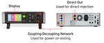
- Coupling Decoupling Network (CDN): Connected to power ports on EUT/DUT for power on Testing
- Direct Out Connections: Connected to ports for power-off direct injection testing
- System Display: Used for selecting criteria and test routines
The direct out is only for power-off testing!
Testing using the direct pulse output out while EUT is powered on will cause damage to the surge generator. The direct out should not be connected to any power conducting lines.
Selecting Test Criteria
Running the surge test can be done either through the software or the front panel of the test system. For the most common requirements (IEC 61000-4-5 etc.), testing is conducted using the display on the front panel of the test system, however, for complex custom test routines software is typically used.
The associated video using the Haefely AXOS5 system walks through how to conduct combination wave surge testing including connections to equipment and selecting testing criteria. This video walks through testing criteria including:
- Changing Voltage Levels
- Selecting Coupling Paths
- Line Synchronization
- Running Basic Tests
Starting Test & Monitoring
Once the criteria have been selected via the front panel or software the test is ready to be run. If specific criteria and routines are created those commence, otherwise the preprogrammed standards will start.
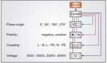
IEC 61000-4-5 has a set number of pulses based upon different testing criteria including phase angle, polarity, coupling and voltage. A visual representation of these requirements can be seen below which is provided in the user manual of the EM Test NX7.
As with most testing it's always recommended to start low and work your way high ensure allowing for better visibility of any issues or failures. This will automatically be the case when selecting most preprogrammed standards, however should also be considered when creating custom test sequences.
Evaluating Results & Test Report
The results should be evaluated based on the underlying standard, however most typically break down results into a few main categories:
- Normal Performance - No noticed impact
- Impacted Performance - Either self recovered or by intervention
- Loss of Function - Degradation of operation not recoverable
Test reports can be generated manually or often through the control software where commonly required information is provided.
Surge Testing Equipment
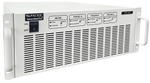
Surge test equipment will include a transient generator able to generate the necessary surges as well as a coupling decoupling network and any auxiliary equipment. If power on testing is needed, a power source will be required to power the equipment under test (EUT). A complete List can be seen below of both the necessary and recommended equipment for surge testing.
- Surge Transient Generator
- Coupling Decoupling Network (CDN)
- Necessary Cabling
- Auxiliary Equipment (if needed)
- Verification Equipment (optional)
Transient generators are devices that replicate surge waveforms in a laboratory setting. Additional information on how to use a transient generator can be found in the previous article we did by clicking here.
Coupling Decoupling Networks (CDNs)
CDNs for power line testing can either be integrated as part of the transient generator, or in the case of three-phase, higher current, or data line testing external. These coupling decoupling networks can either be manual or automatic with the manual requiring manipulation of cabling to change the coupling paths.
Coupling networks designed for 3-phase power line testing come in two different variations, manual and automatic. The difference being an automatic CDN automatically makes the necessary coupling paths based upon software selection, whereas manual the physical connection must be made by the engineer running the test.
The associated video provides an overview of the Teseq CDN 3083-S100 which is a manual CDN designed for testing 3-phase equipment and includes:
- Overview of the CDN
- Components of System
- Changing Coupling Paths
- Connections to Teseq NSG 3060
Surge Testing FAQ
The most common surge test in EMC is IEC 61000-4-5 which is commonly referenced by product-specific requirements.
Surges are commonly mainly in either positive or negative polarity, with the exception being oscillatory transients. Oscillatory transients switch polarity as the value decreases each cycle eventually reaching typical levels.
References:
(1) What Are Surges | NEMA Surge protection Institute. (n.d.). Www.nemasurge.org. https://www.nemasurge.org/history/
(2) https://www.volta.it/wp-content/uploads/2018/06/02-Novit%C3%A0-su-IEC-61000-4-9-10-e-12.pdf
Handbook on EN 61000-4-5: Testing and measurement techniques - Surge immunity test - EMC Standards. (2025). Emcstandards.co.uk. https://www.emcstandards.co.uk/handbook-on-en-61000-4-5-testing-and-measureme
IEC Transient Pulse Immunity | IEC 61000-4-5 Surge. (2019). Ametek-Cts.com. https://www.ametek-cts.com/know-how/iec-transient-pulse-immunity/iec61000-4-5-surge
IEC Transient Pulse Immunity | IEC 61000-4-12 Ring wave. (2019). Ametek-Cts.com. https://www.ametek-cts.com/know-how/iec-transient-pulse-immunity/iec61000-4-12-ring-wave
