Coupling Decoupling Networks (CDNs) - Fundamentals & Applications
What are Coupling Decoupling Networks (CDNs)?
Coupling Decoupling Network (CDNs) are devices that allow for the injection of disturbances on associated EUT/DUT cabling and subsequently removing it prior to auxiliary equipment.
Coupling Decoupling Networks
Coupling Decoupling Networks, commonly called CDNs, serve the purpose of transferring energy or disturbances (coupling) and also removing energy or EMI/noise (decoupling). These are commonly used during EMC immunity testing as a method of injecting noise which the EUT/DUT will be exposed to, then subsequently removing unwanted interference.
The design and capabilities of each network will differ depending upon the application, associated equipment, and underlying standard. The two main advantages of CDNs are:
- Low uncertainty of applied EMI/stress
- Decoupling prior to auxiliary equipment (AE)
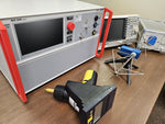
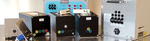
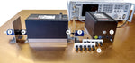
The associated video shows several different conducted RF CDN models as well as how they're setup for testing. During the video a calibration is run using the Teseq NSG 4070 test system providing verification that the setup is correct.
Test Applications
Coupling decoupling networks can be used for both immunity and emissions applications. These devices are commonly used for conducted RF immunity testing to IEC 61000-4-6 as well as emissions tests for CISPR and EN requirements.
The design of these CDNs differ based upon both application, as mentioned above, and type of line. For most applications, with the exception of power mains transient tests, the networks can be used interchangeably regardless of the manufacturer.
Design

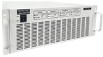
CDNs are generally designed so that one side has a the input (typically the back) and the other the output (typically the front). There is also typically an input connector allowing for connection to a test system that will generate EMI. They are typically designed for a particular type of line, such as power, data, or I/O lines.
Conducted RF CDNs
CDNs designed for conducted RF testing are most commonly used for testing to IEC 61000-4-6 and are the preferred injection method. They are also the most efficient injection device used for conducted RF immunity testing. RF CDNs most commonly designed in accordance with IEC 61000-4-6 and have a common mode impedance of 150 Ohms plus adjustments based on frequency.
The associated diagram illustrates the concept of how CDNs apply the associated disturbance generated by an RF test system on the associated cabling.
CDN Injection Method
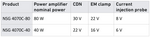
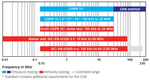
Coupling decoupling networks are the most efficient injection methods allowing for higher levels to be reached with less power. Two other commonly used injection methods for IEC 61000-4-6 involving an EM Clamp and BCI probe require a substantially more power to reach the same test level. The associated image illustrates the different injection methods and anticipated test using the same power.
CDN Selection
CDNs are cable specific, which can lead to multiple being used to test different ports of the equipment under test (EUT). The below diagram references the Teseq CDN guide, which can be accessed by clicking here.

Below is a list of documents that assist with selection and models of CDNs available.
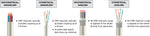
Types of RF CDNs
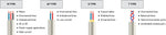
The image below illustrates the generic types of RF CDNs required by the standard. These types are also broken down further into subcategories for specific connection/cable types (IE Coaxial, Unscreened, Etc.).The M Type series are often the most commonly used given they are designed for power lines. Three phase M Type CDNs cannot typically be used for single phase EUT/DUT applications despite having enough connections for the associated lines.
Testing using RF CDNs
Testing for IEC 61000-4-6 is done using the substitution method using a coupling decoupling network. This method uses the calibration data as a main factor in determining the associated level used during testing. The below image illustrates how the adapters and termination load from the calibration are replaced when preforming the test.
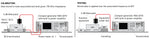
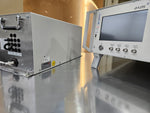
CDN Calibration Setup
During the calibration process the RF systems sweeps the associated frequency levels making the necessary adjustments to meet the associated test level. Once the level is achieved the data is stored to be used later during the testing process. Additional information on conducted RF immunity testing can be found here.
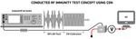
The calibration setup for IEC 61000-4-6 using the CDN injection method can be seen below.
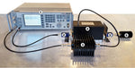
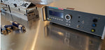
- Conducted RF Test System
- 100Ω Adapters
- 6 dB Attenuator
- Coupling Decoupling Network
- 50 Ω Termination Load
Calibration Adatpers
The 50 Ohm to 150 Ohm adapters provide the 100 Ohm impedance required for IEC 61000-4-6 and are often called just 100 Ohm adapters. The shorting bars provide the connections from the CDN to the adapters and are typically purchased with the associated network. Shorting adapters, also called mating adapters, corresponding the line configuration on the network and cannot typically be used interchangeably.
The 100Ω (50 to 150Ω) adapters can be purchased from Ametek CTS, Com-power, as well as Fischer Custom Communications.
The associated image shows how the shorting and 50 Ohm to 150 Ohm adapters are connected to the CDN.
1) Shorting Adapter 5 Lines
2) Associated 5 Line CDN
3) 50 to 150Ohm Adapters
4) Shorting adapter connected
CDNs for Transient Immunity
Coupling decoupling networks are also commonly used for transient testing of both data and power lines. These devices are typically used for surge, EFT, and ringwave testing and just as with conducted RF testing are required for power on testing. Unlike conducted RF testing however, these CDNs cannot typically be used with our models of transient generators.
Power Line CDNs
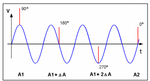
Surge generators use CDNs as a method to inject the transients directly onto different types of lines, most commonly power mains. Given the phase angle requirements of the surge by IEC 61000-4-5 the transient is placed at 0, 90, 180, or 270 degrees on the AC sine wave.
Communication between the generator with the corresponding CDN allows for the pulse to be placed on the selected phase angle. This is a unique requirement of the surge testing and the image show how the placement could potential look on a typical AC mains sine wave.
Electrical fast transients (EFT) are commonly tested to IEC 61000-4-4 which includes both data and power mains line testing. This type of EMI event is often called burst as well, given the fast repetition of quick pulses. This series of pulses doesn't have phase angle requirements, allowing for mixing and matching of equipment.
It is common to see both surge and EFT capabilities in the same CDNs allowing for an easy solution for testing both. This is most typically seen with automatic CDNs allowing for time effective testing rather then swapping out couplers and disconnecting the equipment under test.
Data Line CDNs
Surge testing is also conducted on data and communication lines. This typically done at a lower level then with power lines and requires a specialized CDN designed a particular type of line. The below illustrates common types of data lines and corresponding testing method.
CDNs FAQ
Electrical Fast Transient (EFT) testing is a conducted immunity test designed to subject an EUT to a series of fast rise time and duration pulses to ensure compliance and meet product reliability requirements.
Within EMC EFT is a conducted immunity test designed to simulate a series of fast pulses, commonly called bursts, to evaluate the impact on the function of the EUT.
References:
Application. (2025). Coupling Decoupling Networks (CDN): Conducted Immunity Testing. Com-Power.com. https://www.com-power.com/products/cdns
Interference Technology. (2016, April 28). What’s new: IEC 61000-4-5 Second Edition vs. Third Edition | Interference Technology. Interference Technology. https://interferencetechnology.com/whats-new-iec-61000-4-5-second-edition-vs-third-edition/
Super User. (2025). CDN Coupling Decoupling Networks. Schwarzbeck.com. https://www.schwarzbeck.com/en/produkte/52-cdn-coupling-decoupling-networks/545-cdn-coupling-decoupling-networks.html
What are Coupling Decoupling Networks? - EMC Directory. (2024). Emc-Directory.com. https://www.emc-directory.com/community/what-are-coupling-decoupling-networks-in-emc