
Overview
ISO 10605 is an automotive-based standard that sets forth electrostatic discharge immunity requirements to evaluate electronic modules intended for use with road vehicles. This standard is currently in its second addition published in 2008, it can be purchased from the ISO website. It covers:
- ESD in Assembly
- ESD Caused by Service Staff
- ESD Caused by Passengers(1)
This standard include many common ESD requirements (IEC 61000-4-2) including positive and negative polarity testing, contact and air discharge (explained in more detail on the ESD testing blog), and resistance capacitance network requirements.
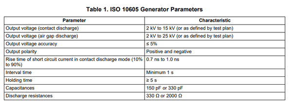
The table below offers the ISO 10605 Generator requirements (Texas Instruments ISO 10605).(2)
Testing Requirements
Simulator/Pulse Generator
This automotive standard, as opposed to IEC 61000-4-2, requires testing up to 25kV or determined by the test plan. It is important that the correct type simulator be used to provide the required voltage. The higher voltage capabilities are often embedded into the simulators with high voltage relays (see block diagram below Teseq NSG 437).
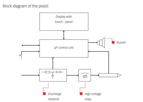
These types of simulators are often broken out by the pistol (handheld device), network (resistance and capacitance module), and the base station. This standard requires the higher voltage levels with four different network configurations:(3)
- 150pF/330Ohm
- 330pF/300Ohm
- 150pF/2kOhm
- 330pF/2kOhm
EN / IEC 61000-4-2 & ISO 10605
These setups can be compared based up on the individual application, of which there are several setups within the automotive ISO standard. This comparison is acting as a brief overview. For specifics and other testing considerations reference the corresponding standard.
Similar Items
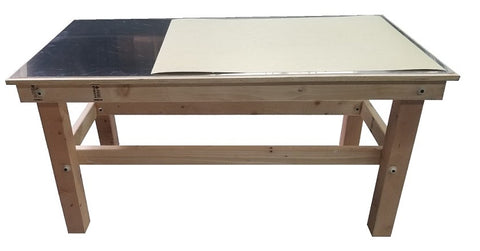
ESD Table - Both standards require all wood tables and ISO 10605 requires the table be between .7 meter and 1 meters tall. This range falls under the guidelines of IEC 61000-4-2, which specifies a .8 meter tall table. This allows for the same table to be used for both setups, given proper planning and consideration. We have another article titled EN/IEC 61000-4-2 Setup - Save Hundreds (Step-by-Step Guide/DIY) detailing how to make a table to ensure it meets electrostatic discharge requirements.
Grounding/Bleed Off Cords/Resistors - Referencing 9.3.2 Test set-up, it requires a safety ground connection (Item #7 of figure 6). Reference (figures 4 and 5) for powered up testing. Given the safety considerations, it is advisable that the resistors be able to withstand ESD occurrences and high voltage wire be used. This same cord and resistor setup can be seen in the commercial standard in figure 5. This allows for the same wires and grounding cords to be used for both.
Ground Reference Plane - The most direct mention of this portion of the setup in ISO 10605 "ground reference plane (GRP), which is placed under the non-conductive table, shall be metallic sheets (e.g. copper, brass or aluminium) and a minimum thickness of 0.25 mm". This meets the requirements of IEC 61000-4-2. Given that the commercial standard has more requirements on the majority of these components, it is ideal to use it as a baseline.

Powered-up Test Setup
Overview
ISO 10605:2008(E) in Annex F is an ESD powered on test, attempting to more accurately replace what occurrences can occur in the real world. This setup has two major components, the metal top (field coupling plane, coupling strips, and discharge islands) and the insulating support.
The below is sized for the minimum requirements, however, the larger section of the metal (field coupling strip) may need to be adjusted to meet EUT requirements (image on the right). Discharges are applied at specific "discharge islands" at given voltages.

Build Considerations
It is important to consider the thickness and type of metal used with this setup.
Using the minimum thickness of common metals specified can lead to a less stable or not supportive base leading to damage to the plane if moved or adjusted.It can also make manufacturing the downward slope of the setup difficult leading to incorrect measurements.
We used copper for our setup cut with exact specifications via water jet laser, this ensured accuracy to the standard.
The non conductive material/insulating is also specified in the standard at prescribed thicknesses and dimensions. It is ideal to have tools that allow for easy cutting and modification of the polystyrene, or other acceptable material meeting relative permittivity requirements.
Keep in mind, there is a somewhat large amount of choices of materials to meet these requirements.
Useful Links
1) ISO Website - Purchase/Preview Standard
2)Texas Instruments - Application Note ISO 10605
3)NoiseKen - Q&A Electrostatic Discharge Simulators (ISO 10605)
InCompliance Magazine - Human-Body Model and Electrostatic Discharge (ESD) Tests









1 comment
canadian pharmacy
Your style is very unique in comparison to other folks I’ve read stuff from. I appreciate you for posting when you have the opportunity, Guess I will just bookmark this page.