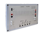
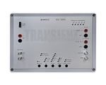
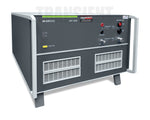
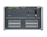
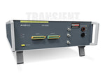
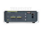
EM Test RCB 200N1
Related Equipment
Description
As per FORD FMC1278 and EMC-CS-2009.1 a part of the test pulses is not generated using a transient pulse generator similar to the ones defined as per ISO 7637 but being based on a circuitry including a Potter & Brumfield 12VAC relay and specifically defined components such as inductors, capacitors, resistors and switches with the aim of simulating "real-world transients".
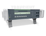
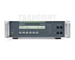
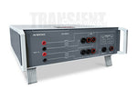
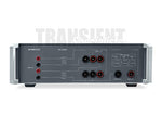
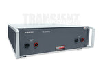
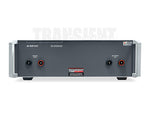
The EM TEST RCB 200N1 transient generator meets the requirements set out by the FORD FMC1278 and EMC-CS-2009.1 standard document. It is built using the components outlined in Figure F-1 to generate pulses such as CI 220 A1, A2-1, A2-2, C-1 and C-2, CI 260 F and RI 130 A2-1 and A2-2 for which the RCB 200N1 is built into a metal housing. For RI 130 testing the RCB 200N1 offers BNC-type coaxial outputs to connect the specified test fixture needed for this particular test.
- TECHNICAL DATA
- RCB 200N1
- Circuitry as per Annex F, Figure F-1 with the following components:
- Resistor R1
- 51 ohms, 25W
- Resistor R2
- 220 ohms +/- 5%, 2W
- Resistor R3
- 33 ohms +/- 5%, 10W
- Resistor R4
- 6 ohms +/- 5%, 50W
- Capacitor C1
- 100 nF capacitor, 400V
- Inductor L1
- 5 uH inductor (Osborne transformer part no. 8745)
- Inductor L2
- 100 mH inductor (Osborne transformer part no. 32416)
- Diode D1
- Zener diode, 39V, 5W
- Transistor Q1
- NPN transistor
- SW0 - SW4
- Single Throw Switch
- RLY1
- 12 volt AC relay, NC contact used (Potter&Brumfield KUP-14A15-12)




 info@transientspecialists.com