

 Contact Us
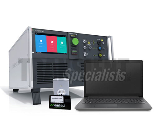
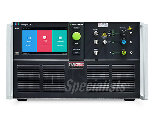


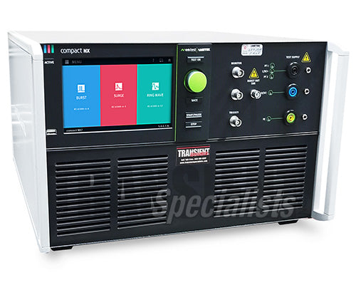
EM Test Compact NX7 - 7kV Transient Pulse System

EM Test NX7 - Rental Immunity Accesories


Description
Overview
The compact Next Generation NX7 is the most versatile tester to address transient and power fail requirements for both international and commercial standards.
Featuring an easy-to-use color touch screen, the NX7 provides an economical solution for pre-compliance immunity testing as well as full-compliance testing and CE Marking. Its internal single-phase Coupling/Decoupling Network (CDN) can be extended for testing three-phase EUTs by means of an automatically controlled external CDN up to 200 A per phase. AMETEK CTS supplies a large range of accessories for various applications such as magnetic field tests and more.
Data Sheet User ManualSpecifications
|
Common Standards |
EN/IEC 61000-4-4, EN/IEC 61000-4-5, EN 61000-4-12 ANSI C62.41, C62.45, UL 1449 |
|
BURST MODULE |
|
|
Test voltage |
200 V - 5,500 V ± 10%; 100 V - 2,750 V ± 10% into 50 ohm |
|
Pulse shape |
5/50 ns into 50 ohm and 1,000 ohm |
|
Rise time tr |
5 ns ± 30% into 50 ohm; 5 ns ± 30% into 1,000 ohm |
|
Pulse width td |
50 ns ± 30% into 50 ohm; 50 ns -15/+100 ns into 1,000 ohm |
|
Source impedance |
50 ohm |
|
Polarity |
Positive, negative |
|
TRIGGER CIRCUIT |
|
|
Trigger of bursts |
Automatic, manual, external |
|
Synchronization |
0° - 360°, resolution 1° (16 - 500 Hz) |
|
Burst duration (td) |
td = 0.10 ms - 9,999 ms |
|
Repetition rate (tr) |
tr = 10 ms - 9,999 ms |
|
Spike frequency |
f = 1 Hz - 1,000 kHz |
|
Test duration |
T = 0:01 min - 99:59 min T > 99:59 min --> endless |
|
OUTPUTS |
|
|
Direct |
Via 50 ohm coaxial connector |
|
Coupling mode |
L, N, PE; all combinations |
|
EUT supply |
AC: 300 V / 400 V, 50/60 Hz DC: 300 V / 400 V, Current: 16 A / 32 A |
|
CRO trigger |
5 V trigger signal for oscilloscope |
|
TEST ROUTINES |
|
|
Quick Start |
On-line adjustable parameters, easy-to-use |
|
Standard Test routines |
As per IEC/EN 61000-4-4, Levels 1 - 4 As per IEC/EN 61000-6-1, -6-2 As per ECE R-10 Rev5 |
|
Extended Test routines |
Change voltage after T, Frequency sweep within one burst, Frequency sweep with constant number of pulses, Frequency sweep with constant burst duration, Synchronous burst release, Random burst release |
|
OPTIONS |
|
|
CCI |
Capacitive coupling clamp as per IEC/EN 61000-4-4 |
|
CCI PVKIT 1 |
Adapter set for capacitive coupling clamp calibration included: - Transducer plate as per IEC/EN 61000-4-4 Ed 3.0, - Support for positioning the PVF 50 on 100 mm height as the capacitive coupling clamp, - PVF AD 3 to match the Transducer plate to the PVF 50 |
|
PVF 50 |
100:1 divider, 50 ohm |
|
PVF 1000 |
500:1 divider, 1,000 ohm |
|
PVF BKIT 1 |
Kit for burst pulse verification consisting of PVF 50, PVF 1000 and adapter for EUT port in a plastic case for storage |
|
PVF AD 1 |
Adapter to match PVF 50 load resistor to the EUT supply of NX-series coupling network, 3-phase coupling network |
|
ITP |
Immunity test probes (electrical field generation) |
|
ITP/H |
Immunity test probe (magnetic field generation) |
|
SURGE MODULE |
|
|
Voltage (o.c.) |
200 V - 7,000 V ± 10% |
|
Pulse front time |
1.2 µs ± 30% |
|
Pulse duration |
50 µs ± 20% |
|
Current (s.c.) |
Max. 3,500 A ± 10% |
|
Pulse front time |
8 µs ± 20% |
|
Pulse duration |
20 µs ± 20% |
|
Polarity |
Positive, negative, alternate |
|
TRIGGER CIRCUIT |
|
|
Release of pulses |
Automatic, manual, external |
|
Synchronization |
0° - 360°, resolution 1° |
|
Repetition rate |
max. 1 Hz (1 s - 9,999 s) |
|
Event counter |
1 - 99,999, selectable |
|
OUTPUTS |
|
|
Direct |
Via HV connectors for external coupling networks |
|
Coupling mode |
Line to line Line(s) to ground |
|
EUT supply |
AC: 300 V / 400 V, 50/60 Hz DC: 300 V / 400 V, Current: 16 A / 32 A |
|
CRO trigger |
5 V trigger signal for oscilloscope |
|
MEASUREMENTS |
|
|
CRO Û-monitor |
10 Vp at 7,000 V |
|
CRO Î-monitor |
10 Vp at 3,500 A |
|
Peak voltage |
7,000 V in the touch display |
|
Peak current |
3,500 A in the touch display |
|
Overcurrent protection |
Breaks the Surge test when the surge current is over the limit, Limiter for differential mode, Limiter for common mode |
|
EUT current |
RMS current, Range 50 A, < ±5% |
|
EUT overcurrent protection |
Breaks the test when the EUT current is over the limit, |
|
TEST ROUTINES |
|
|
Quick Start |
One-line adjustable parameters, easy-to-use |
|
Standard Test routines |
As per IEC/EN 61000-4-5, As per IEC/EN 61000-6-1, As per IEC/EN 61000-6-2, Manual Standard Test routine |
|
Extended Test routines |
Voltage iteration after n pulses, Angle iteration stepwise, Phase angle randomiteration, Change coupling after n pulses, Change phase angle after n pulses |
|
Pulsed Magnetic Field |
as per IEC/EN 61000-4-9 Test levels 100, 300 and 1,000A/m Test level continuously adjustable under Quick Start |
|
OPTIONS |
|
|
DCD 7 sr-4-x |
Coupling network for 4 signal/data lines as per IEC/EN 61000-4-5 Ed 3.0 |
|
DCD 7 sr-8-x |
Coupling network for 8 signal/data lines as per IEC/EN 61000-4-5 Ed 3.0 |
|
DCD 7 st-4-1 |
Coupling/decoupling network for 4 unshielded symmetrical lines (communication lines) as per IEC/EN 61000-4-5 Ed 3.0 (fig. 10) |
|
DCD 7 st-8-1 |
Coupling/decoupling network for 8 unshielded symmetrical lines (communication lines) as per IEC/EN 61000-4-5 Ed 3.0 (fig. 10) |
|
HSC 4-8 |
Coupling/decoupling network for testing unshielded and shielded high-speed communication lines (Ethernet lines) |
|
SPN 508N1 |
Surge protection network to reduce the surge voltage <10 V at the A |
|
POWER FAIL MODULE |
|
|
As per |
IEC/EN 61000-4-11, IEC/EN 61000-4-29 and IEC/EN 61000-6-1, -6-2 |
|
Channel PF1/PF2 |
AC voltage: max. 300 V / 400 V AC current: max. 16 A / 32 A DC voltage: max. 300 V / 400 V DC current: max. 16 A / 32 A |
|
Frequency |
16 Hz - 500 Hz and DC |
|
Switching time |
> 1 µs < 5 µs into a 100 ohm resistive load (SVP 100) |
|
Inrush current |
> 500 A |
|
Protection |
Both channels are protected against short-circuit conditions. |
|
TRIGGER CIRCUIT |
|
|
Trigger of events |
Automatic, manual, external |
|
Synchronization |
0° - 360°, resolution 1° (16 - 500 Hz) |
|
Repetition rate |
10 ms - 9,999 s |
|
Event duration |
10 µs - 99.999 s |
|
Event counter |
1 - 99,999, selectable |
|
OUTPUTS |
|
|
EUT terminals |
L, N and PE |
|
CRO trigger |
5 V trigger signal for oscilloscope |
|
MEASUREMENTS |
|
|
EUT voltage (rms) |
In the touch screen |
|
EUT current (rms) |
In the touch screen |
|
MON V |
Measurement of the EUT voltage, built-in divider: 300 V: 42,5:1, 10 V =425 Vpk, 400 V: 56.6:1, 10 V =566 Vpk |
|
MON I |
Measurement of the EUT current, 16 A: 7 A/V; 10 V =70 Apk, 32 A: 10 A/V; 10 V =100 Apk |
|
TEST ROUTINES |
|
|
Quick Start |
On-line adjustable parameters, easy-to-use |
|
Standard Test routines |
As per IEC/EN 61000-4-11 for AC supplies As per IEC/EN 61000-4-29 for DC supplies As per EN 61000-6-1, -6-2 Manual Standard Test routine |
|
Extended Test routines |
Voltage variation, control of an external variac, Phase angle iteration, Reduced time iteration, Angle inverse mode, Random by step and list Inverse mode |
|
50/60 Hz magnetic field |
As per IEC/EN 61000-4-8 Test levels 1, 3, 10 and 30 A/m with external current transformer MC 2630, Test levels 100, 300 and 1,000 A/m with external current transformer MC 26100 |
|
OPTIONS |
|
|
TVT 1-250-16 |
Tapped autotransformer as per IEC/EN 61000-4-11 Ed 2.0 |
|
TVT 1-250-16 |
Tapped autotransformer as per IEC/EN 61000-4-11 Ed 2.0 with automatic change of tap |
|
variac NX 1-260-16 |
Motorized variac (0 - 260 V, 16 A) |
|
variac NX 1-260-32 |
Motorized variac (0 - 260 V, 32 A) |
|
MFC 1000 |
Magnetic field coil, 1 m x 1 m, up to >1000 A/m (with trolley) |
|
MFC 1000.1 |
Magnetic field coil, 1 m x 1 m, up to >1000 A/m (with stand) |
|
MFT 30 |
Current transformer for magnetic fields up to 30 A/m |
|
MFT 100 |
Current transformer for magnetic fields up to 1,000 A/m |
|
SVP 1700 |
Calibration box for inrush current verification as per IEC/EN 61000-4-11 |
|
SVP 100 |
100 ohm low inductive load resistor, for rise and fall time verification |
|
RINGWAVE MODULE |
|
|
Test voltage |
200 V - 7,000 V ± 10% |
|
Voltage |
Wave shape (open circuit) |
|
Rise time |
0.5 µs ± 30% (first peak) |
|
Oscillation frequency |
100 kHz ± 10% |
|
Decaying |
Peak 2 to peak 1 = 40 - 110% Peak 3 to peak 2 = 40 - 80% Peak 4 to peak 3 = 40 - 80% |
|
Current |
Wave shape (short circuit) |
|
Rise time |
0.2 µs < tr <= 1.0 µs |
|
Oscillation frequency |
100 kHz ± 10% |
|
Source impedance |
12 ohm, 30 ohm, 50 ohm |
|
Peak current |
As per selected source impedance |
|
Polarity |
Positive, negative, alternate |
|
TRIGGER CIRCUIT |
|
|
Release of pulses |
Automatic, manual, external |
|
Synchronization |
0° - 360°, resolution 1° |
|
Repetition rate |
max. 1 Hz (1 s - 9999 s) |
|
Event counter |
1 - 99,999, selectable |
|
OUTPUTS |
|
|
Direct |
Via HV-safety lab connectors |
|
Coupling mode |
L, N, PE; line to line and line(s) to ground |
|
DUT supply |
AC: 300 V / 400 V, 50/60 Hz DC: 300 V / 400 V, Current: 16 A / 32 A |
|
CRO trigger |
5 V trigger signal for oscilloscope |
|
MEASUREMENTS |
|
|
CRO Û-monitor |
10 Vp at 7,000 V |
|
CRO Î-monitor |
10 Vp at 3,500 A |
|
Peak voltage |
500 V - 7000 V in the touch display |
|
OPTIONS |
|
|
DCD 7 sr-4-x |
Coupling network for 4 signal/data lines as per IEC/EN 61000-4-12 Ed 3.0 |
|
DCD 7 sr-8-x |
Coupling network for 4 signal/data lines as per IEC/EN 61000-4-12 Ed 3.0 |
|
HSC 4-8 |
Coupling/decoupling network for testing unshielded and shielded high-speed communication lines (Ethernet lines) |
|
SPN 508N1 |
Ringwave protection network to reduce the surge voltage <10 V at the AE |
|
TSURGE MODULE, (OPTIONAL) |
|
|
Test voltage (o.c.) |
200 V - 7,000 V ± 10% |
|
Energy storage capacitor |
20 µF |
|
Polarity |
Positive, negative, alternating |
|
|
As per ITU and ETSI recommendations |
|
Front time |
10 µs ± 30% |
|
Pulse duration |
700 µs ± 20% |
|
|
As per FCC part 68, Pulse B |
|
Front time |
9 µs ± 30% |
|
Pulse duration |
720 µs ± 20% |
|
Output current @25 ohm output |
5 A - 175 A (short circuit) |
|
Rise time |
5 µs ± 30% |
|
Pulse duration |
320 µs ± 20% |
|
|
As per IEC 61000-4-5 |
|
Rise time |
10 µs ± 30% |
|
Pulse duration |
700 µs ± 20% |
|
Output current @25 ohm output |
5 A - 175 A (short circuit) |
|
Rise time |
5 µs ± 20% |
|
Pulse duration |
320 µs ± 20% |
|
TRIGGER CIRCUIT |
|
|
Trigger of events |
Automatic, manual, external |
|
Repetition rate |
max. 0.33 Hz (3 s - 999 s) |
|
Event counter |
1 - 99,999, selectable |
|
OUTPUTS |
|
|
As per ITU |
For 2-wire T1/T2 with 25 ohm each |
|
As per FCC part 68 |
For 2-wire T1/T2 with 25 ohm each |
|
As per IEC 61000-4-5 Ed 3.0 |
For 4-wire T1/T2/T3/T4 with 25 ohm each |
|
|
For other requirements special output configurations are available |
|
OPTIONS |
|
|
DCD 7 st-4-1 |
Coupling/decoupling network for unshielded symmetrical lines (communication lines) as per IEC/EN 61000-4-5 Ed.3 (fig. 10) for 4 lines |
|
DCD 7 st-8-1 |
Coupling/decoupling network for unshielded symmetrical lines (communication lines) as per IEC/EN 61000-4-5 Ed.3 (fig. 10) for 8 lines. |
|
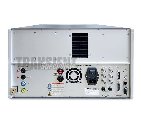
INTERFACES |
|
|
Serial interface |
2 x USB A for memory stick, 1 x USB B for service only, Opto - Link to USB for remote |
|
Lan |
Ethernet for remote |
|
Analog output |
0 - 10 VDC to control an external transformer |
|
Sys.link |
26 pin high density connector to control an external coupling network |
|
Fail inputs |
EUT monitoring via input (one each) EUT Monitor 1 EUT Monitor 2 |
|
Ext. Trigger |
BNC Ext. Trigger IN pos slope 5 V |
|
Ext. Sync Input |
Differential input, 50 V - 690 VAC, 2 x 4 mm MC Safety connectors |
|
DIMENSIONS AND WEIGHT |
|
|
16 A models |
19"/6 HU, 500 mm deep, 19"/9 HU, with telecom module, approx. 30 kg |
|
32 A models |
19"/6 HU, 500 mm deep, 19"/9 HU, with telecom module, approx. 40 kg |
|
ENVIRONMENT |
|
|
Temperature |
10 °C to 35 °C (Operation) -10 °C to 60 °C (Storage) |
|
Humidity |
30 % to 70 %, non condensing |
|
Atmospheric pressure |
86 kPa (860 mbar) to 106 kPa (1,060 mbar) |
|
MAINS |
|
|
Supply voltage |
85 V - 264 V |
|
Frequency |
50/60 Hz |
|
Power |
approx. 75 W |
|
Fuses |
115 V: 2 x 4 A slow blow, 230 V: 2 x 2 A slow blow |
|
SAFETY |
|
|
Safety standard |
IEC/EN 61010 |
|
Security circuit |
Control input (24 VDC) |
|
Warning lamp |
Floating contact (max. 60 V/2 A) |
Standards
Widely Used Standards
This list is a more comprehensive list of all the standards covered with this conducted immunity generator. For assured compliance to a particular standard, confirm prior to rental. This EM Test equipment has the ability to either cover all, or part of the standards below.
- ANSI/IEEE C37.90
- ANSI/IEEE C62.41
- ECE-R10
- EN 300329
- EN 300340
- EN 300342-1
- EN 300386 V1.3.2
- EN 301489-1
- EN 301489-17
- EN 301489-24
- EN 301489-7
- EN 50121
- EN 50121-3-2
- EN 50121-4
- EN 50121-5
- EN 55024
- EN 61000-4-11
- EN 61000-4-29
- EN 61000-4-4
- EN 61000-4-5
- EN 61000-4-8
- EN 61000-4-9
- EN 61000-6-1
- EN 61000-6-2
- FCC 97-270 (part 68)
- IEC 60255-22-5
- IEC 61000-4-11
- IEC 61000-4-12
- IEC 61000-4-29
- IEC 61000-4-4
- IEC 61000-4-5
- IEC 61000-4-8
- IEC 61000-4-9
- IEC 61326
- IEC 61850-3
- ITU-T K.20
- ITU-T K.21
- ITU-T K.41
- ITU-T K.45
All Accessories
Rent coupler decoupler networks (CDN)s from a preferred rental partner of Ametek CTS.
Take advantage of A2LA ISO 17025 calibrations and fast deliveries!
NX7 Full Accessory List
| Item | Capabilities |
| Variac NX 1-260-16 | A motorized variac is offered as an alternative to the tapped autotransformers for voltage dips/interruptions and voltage variation tests as per IEC/EN 61000-4-11. The motorized variac can also be used for automated magnetic field tests. |
| V 4780 |
The V 4780 tapped autotransformer is designed to supply the required voltages as per IEC/EN 61000-4-11 to perform voltage dips. |
| V 4780S2 |
The V 4780S2 is an automatic tapped auto transformer, designed to supply the required voltages as per IEC/EN 61000-4-11 to perform voltage dips and interruptions. Compared to the manually operated V 4780, the V 4780S2 model offers automatic change of taps according to the selected voltage level. |
| DCD 5 SR- and ST-Series |
DCD 5 sr- and st-series coupling/decoupling networks are available to perform surge tests on I/O lines, signal/data lines and telecom lines as per IEC/EN 61000-4-5 Ed 3.0 The DCD 5 sr- series couples surge and ring wave impulses to unsymmetrical signal and datalines for 4 or 8 lines. The DCD 5 st- series couples surge and telecomsurge impulses to symmetrical signal and datalines for 2 or 4 pairs of signal lines. |
| MFC 1000 |
The MFC 1000 is a 1m x 1m magnetic field coil as specified in IEC/EN 61000-4-8 and IEC/EN 61000-4-9. Its design allows easy moving of the coil. The field coil is adjustable in height and allows for 360 degree rotation. |
| CCI |
Capacitive coupling clamp as per specification IEC/EN 61000-4-4. |
| ITP |
ITP is a tool being used for development test. It consists of a variety of electrical field probes. The probes allow to locate weak points within a system or on a PCB. The burst pulse is used to generate the disturbance signal. |
| PVF BKIT 1 |
As per IEC/EN 61000-4-4 the characteristic of the burst generator needs to be verified with two different loads, 50 ohm and 1,000 ohm. EM TEST offers a calibration kit consisting of the two loads and an adapter to verify the pulses at the EUT output. |
| CCI PVKIT 1 |
The IEC/EN 61000-4-4 Ed 3.0 standard published in 2012 recommends the calibration of the capacitive coupling clamp into a 50 ohm coaxial load. |
| CA PFS |
The inrush current capability of PowerFail generators as per EN/IEC 61000-4-11 and IEC/EN 61000-4-34 can be verified by means of the CA PFS circuit box. The circuit is specified in Annexes of EN/IEC 61000-4-11, -34 Standard. The inrush current is measured by means of the built-in current delivering a voltage signal of 10 mV/A at the corresponding BNC output connected to an oscilloscope with selected 1 MOhm input impedance. |
| HSC 4-8 |
The HSC 4-8 from AMETEK CTS is the first coupling/decoupling network available on the market to couple Surge onto shielded and unshielded high-speed communication lines with data rates up to 1,000MBit/s. |
NX7 Series
|
ACCESSORIES INCLUDED |
|
|
Mains supply |
Plug depends on the country of use |
|
EUT supply |
Plug depends on the country of use |
|
EUT adapter |
Socket depends on the country of use |
|
|
Operation manual, Calibration certificate, iec.control remote control software |
|
OPTIONS |
|
|
coupling NX7 |
3-phase coupling/decoupling networks as per - IEC/EN 61000-4-4 and - IEC/EN 61000-4-5 up to 200 A per phase |
|
iec.control |
Remote control and documentation software, including standard test routines and reporting capabilities. included: UOC USB-Optolink Converter |
|
UOC |
USB-Optolink Converter, Optical Fibre cable, 5 m |
|
AVAILABLE MODELS: 300 V |
|
|
Compact NX7 series |
Compact simulator with |
|
compact NX7 bsp-1-300-16 |
Burst, Surge, Power Fail, 300 V, 16 A |
|
compact NX7 bspr-1-300-16 |
Burst, Surge, Power Fail, Ringwave 300 V, 16 A |
|
compact NX7 bspt-1-300-16 |
Burst, Surge, Power Fail, Telecom Surge 300 V, 16 A |
|
compact NX7 bsprt-1-300-16 |
Burst, Surge, Power Fail, Ringwave, Telecom Surge 300 V, 16 A |
|
compact NX7 bs-1-300-16 |
Burst, Surge 300 V, 16 A |
|
compact NX7 bst 1-300-16 |
Burst, Surge, Telecom Surge 300 V, 16 A |
|
compact NX7 sp-1-300-16 |
Surge, Power Fail, 300 V, 16 A |
|
compact NX7 st-1-300-16 |
Surge, Telecom Surge 300 V, 16 A |
|
AVAILABLE MODELS: 400 V |
|
|
compact NX7 bsp-1-400-32 |
Burst, Surge, Power Fail, 400 V, 32 A |
|
compact NX7 bspr-1-400-32 |
Burst, Surge, Power Fail, Ringwave, 400 V, 32 A |
|
compact NX7 bspt-1-400-32 |
Burst, Surge, Power Fail, Telecom Surge, 400 V, 32 A |
|
compact NX7 bsprt-1-400-32 |
Burst, Surge, Power Fail, Ringwave, Telecom Surge, 400 V, 32 A |
|
AVAILABLE MODELS: WITHOUT COUPLER, 400 V (P-N), 3 X 690 V (P-P) |
|
|
|
These models requires an external coupler 3 x 690 V |
|
compact NX7 bs-0-690 |
Burst, Surge |
|
compact NX7 bsr-0-690 |
Burst, Surge, Ring wave |
|
|
|


