


EM Test UCS 500N7
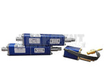
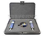
Included Accessories
Can't find something? Contact UsRelated Equipment
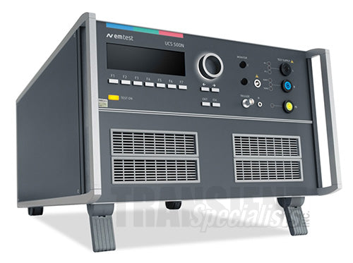
Description
The UCS 500N7 ultra-compact simulator is the most versatile tester to cover transient and power fail requirements according to international standards (basic and generic standards) and product/ product family standards with voltage capability of up to 7.0 kV. Apart from the IEC/EN 61000-4-5 standard for surge testing it also complies to ANSI/IEEE C62.41 for surge and ringwave testing.
The UCS 500N7 not only represents the most economic solution for full-compliant immunity tests and CE Marking but goes far beyond. Having a built-in CDN for single phase DUTs it can be extended for testing three-phase DUTs by means of an automatically controlled external coupling network up to 100A. EM TEST supplies a large range of accessories for various applications.
Benefits
The UCS 500N7 includes everything necessary to conduct fully compliant tests at levels that go far beyond common test requirements.
Surge can be test up to 7.0kV either according to IEC/EN 61000-4-5 or ANSI/IEEE C62.41. The UCS 500N7 offers an integrated Ringwave module (optional) as per ANSI/IEEE C62.41 and IEC/EN 61000-4-12 for ringwave tests on mains supply lines.
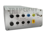
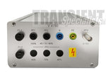
The UCS 500N7 can be operated manually from the front panel or by remote via the built-in USB or GPIB interface. Fail inputs allow to control an ongoing test sequence based on the status of the DUT. Monitoring outputs (BNC) are offered for easy signal measurement and verification. Safety features such as interlock and warning lamp control are available.
Pre-programmed Standard Test routines allow highest user convenience. Still the UCS 500N7 offers the Quick Start test routine where parameters can be changed on-line during the test to evaluate the susceptibility level of an individual DUT, a most appreciated benefit for tests at development stage.
Operation
Front panel menu and function keys enable the user to program his test routines quickly and accurately. The cursor allows fast control of all test parameters of the programmed routine, thus test procedures are simplified and confidence is generated that every step is carried out correctly.
Software
Outstanding user convenience, clearly structured windows and operation features and the EM TEST standards library along with the flexibility to generate user specific test sequences very easily are the main features of iec.control software.
The software is automatically configured according to the connected EM TEST generators. Extensive reporting capabilities help the user to create test reports that meet international requirements.
iec.control is supported by Windows XP, Windows Vista, Windows 7 and Windows 8. Remote control is achieved either via USB or GPIB. iec.control supports a wide range of GPIB cards of National Instruments.
- Specifications:
- Burst Module
- As per EN/IEC 61000-4-4 and EN 61000-6-1, -6-2
- Test voltage
- 200V - 5,500 V +/- 10%;
100V - 2,750 V +/- 10% into 50 ohm - Pulse shape
- 5/50 ns into 50 ohm and 1,000 ohm
- Rise time tr
- 5 ns +/- 30% into 50 ohm; 5 ns +/- 30% into 1,000 ohm
- Pulse width td
- 50 ns +/- 30% into 50 ohm;
50 ns -15/+100 ns into 1,000 ohm - Source impedance
- 50 ohm
- Polarity
- Positive, negative
- Trigger Circuit
- Trigger of bursts
- Automatic, manual, external
- Synchronization
- 0 - 360 Degrees, resolution 1 degree (16 - 500 Hz)
- Burst duration
- td = 0.10 ms - 999 ms
- Repetition rate
- tr = 10 ms - 9,999 ms
- Spike frequency
- f = 0.1 kHz - 1,000 kHz
- Test duration
- T = 0:01 min - 99:59 min
T > 99:59 min --> endless - Outputs
- Direct
- Via 50 ohm coaxial connector
- Coupling mode
- L, N, PE; all combinations
- DUT supply
- AC: 300 V/16 A; 50/60 Hz
DC: 300 V/16 A - CRO trigger
- 5 V trigger signal for oscilloscope
- Test Routines
- Quick Start
- On-line adjustable parameters, easy-to-use
- Standard Test routines
- As per IEC 61000-4-4,
Levels 1 - 4 As per EN 61000-6-1, -6-2
Manual Standard Test routine - User Test routines
- Synchronous burst release, Random burst release, Change voltage after T, Frequency sweep within one burst,
Frequency sweep with constant number of pulses, Frequency sweep with constant burst duration, Change polarity after T - Surge Module
- As per EN/IEC 61000-4-5 Ed 3.0 and EN 61000-6-1, -6-2
- Voltage (o.c.)
- 250 V - 7,000 V +/- 10%
- Pulse front time
- 1.2 us +/- 30%
- Pulse time to half value
- 50 us +/- 20%
- Current (s.c.)
- Max. 3,500 A +/- 10%
- Pulse front time
- 8 us +/- 20%
- Pulse time to half value
- 20 us +/- 20%
- Polarity
- Positive, negative, alternating
- Counter
- 1 - 30,000 or endless, selectable
- Trigger
- Release of pulses
- Automatic, manual, external
- Synchronization
- 0 - 360 degrees, resolution 1 degree
- Repetition rate
- Max. 0.5 Hz (2 s - 999 s)
- Outputs
- Direct
- Via HV connectors for external coupling networks (Zi = 2 ohm with optional adapter IMN 2)
- Coupling modes
- As per IEC 61000-4-5: Line to line with 2 ohm, Line(s) to ground with 12 ohm
As per ANSI/IEEE C62.41: Line to line with 2ohm, Line(s) to ground with 2ohm - DUT supply
- AC: 300 V/16 A; 50/60 Hz
DC: 300 V/16 A - CRO trigger
- 5 V trigger signal for oscilloscope
- Measurements
- CRO U-monitor
- 10 Vp at 7,000 V
- CRO I-monitor
- 10 Vp at 3,500 A
- Peak voltage
- 7,000 V in the LCD display
- Peak current
- 3,500 A in the LCD display
- Overcurrent protection
- Breaks the Sureg test when the surge current is over the limit, Limitter for differential mode, Limitter for common mode
- Test Routines
- Quick Start
- One-line adjustable parameters, easy-to-use
- Standard Test routines
- As per IEC 61000-4-5, Levels 1 - 4
As per EN 61000-6-1, -6-2
Manual Standard Test routine - User Test routines
- Change polarity after n pulses
Change coupling after n pulses
Change voltage after n pulses
Change phase angle after n pulses - Pulsed Magnetic Field
- As per IEC 61000-4-9
Test levels 100, 300 and 1,000 A/m
Test level steplessly adjustable under Quick Start - Ringwave Module
- As per ANSI/IEEE C62.41 and EN/IEC 61000-4-12
- Test voltage
- 250 V - 6,000 V +/- 10%
- Voltage
- Wave shape (open circuit)
- Rise time (first peak)
- 0.5 us +/- 30%
- Oscillation frequency
- 100 kHz +/- 10%
- Decaying
- Peak 2 to peak 1 = 40 - 110%
Peak 3 to peak 2 = 40 - 80%
Peak 4 to peak 3 = 40 - 80% - Current
- Wave shape (short circuit)
- Rise time
- <= 1.0 us
- Oscillation frequency
- 100 kHz +/- 10%
- Source impedance
- 12 ohm and 30 ohm
- Peak current
- As per selected source impedance
- Polarity
- Positive, negative
- Trigger
- Release of pulses
- Automatic, manual, external
- Synchronization
- 0 - 360 degrees, resolution 1 degree
- Repetition rate
- max. 1 Hz (1 s - 999 s)
- Outputs
- Direct
- Via HV-safety lab connectors
- Coupling mode
- L, N, PE; line to line and line(s) to ground
- DUT supply
- AC: 300 V/16 A; 50/60 Hz
DC: 300 V/16 A - CRO trigger
- 5 V trigger signal for oscilloscope
- Quick Start
- On-line adjustable parameters, easy-to-use

 info@transientspecialists.com